190-01182-02 GTR 225/GNC 255 TSO Installation Manual
Rev. F Page 6-19
6.6 Ground Checks (Normal Mode)
6.6.1 Discrete Input Checkout
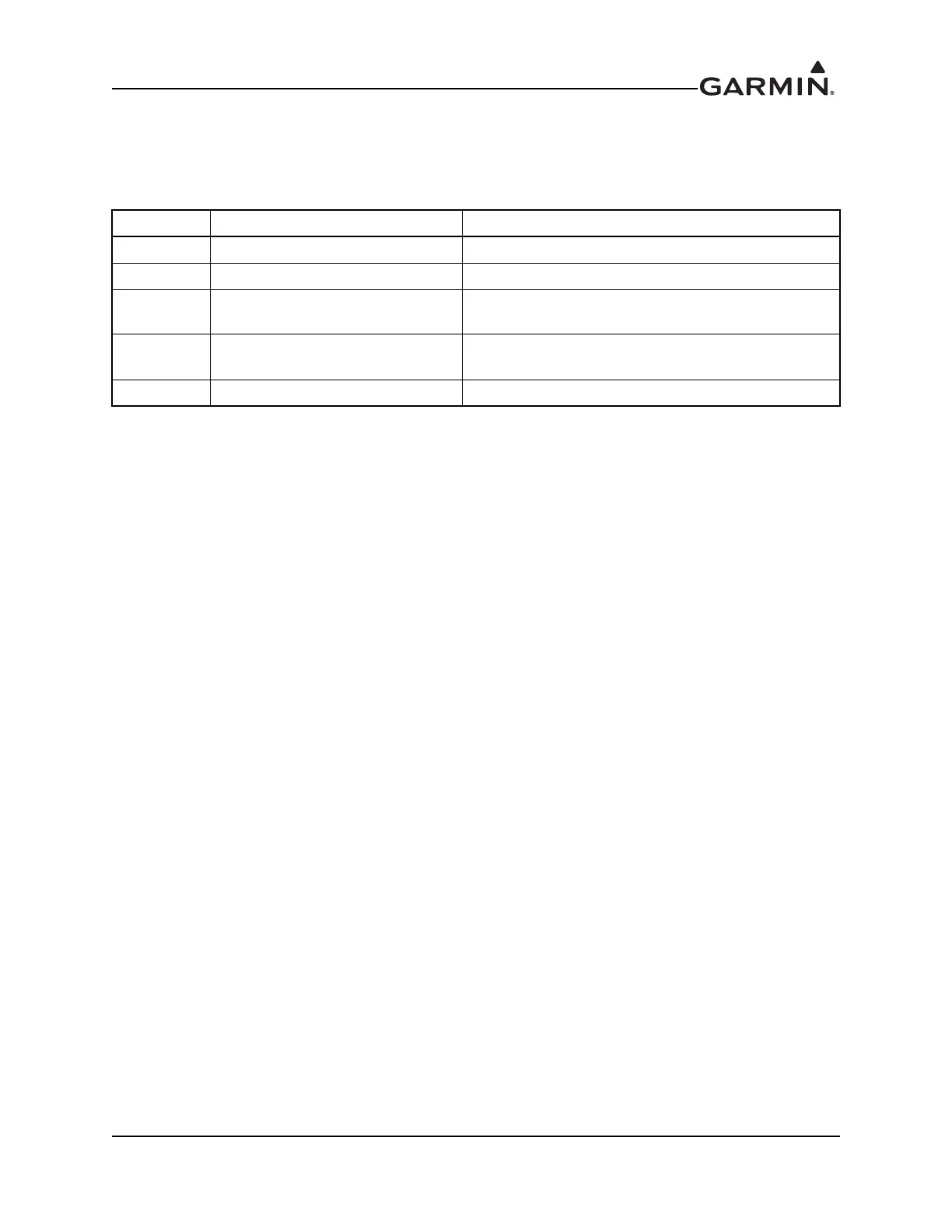
Table 6-15 Discrete Input Pins
If a switch is connected to any pins listed in table 6-15, perform the following procedure:
1. Exercise the switch source for each of the switches that are connected.
2. Verify that the function controlled by the switch operates as intended.
3. Verify the wiring between the GTR/GNC and the switch if not operating as intended.
6.6.2 VHF NAV Checkout
Check the VOR reception with ground equipment, operating VOT or VOR, and verify audio and Morse
code ID functions, if possible. Tune a localizer frequency and verify the CDI needle, NAV flag, VDI
needle and GS flag operation.
6.6.3 NAV Audio Check (Audio Panel Installations) (GNC Only)
Ensure the audio panel is powered on and perform the following steps:
1. Plug in a headset at pilot and copilot position.
2. Tune the GNC NAV receiver to a local VOR station
3. Select NAV audio on the audio panel.
4. Ensure the Morse code identifier is being received over the crew headsets.
5. Verify the wiring connections to the audio panel, if the audio is not heard.,
6. Ensure the audio volume is sufficient for all anticipated cockpit noise conditions.
Pin Pin Name Description
P2001-12 INTERCOM ENABLE* Enables the intercom function on the GTR/GNC.
P2001-27 COM REMOTE TRANSFER* Flip-flops the active and standby COM frequencies.
P2001-28 COM REMOTE TUNE UP*
Scrolls up through the preset COM frequencies in
the standby frequency field.
P2001-29 COM REMOTE TUNE DOWN*
Scrolls down through the preset COM frequencies in
the standby frequency field.
P2002-28 VLOCK REMOTE TRANSFER Flip-flops the active and standby NAV frequencies.
 Loading...