190-01182-02 GTR 225/GNC 255 TSO Installation Manual
Rev. F Page 5-5
5.2 Power, Lighting, And Antennas
Information about power input requirements, lighting bus input, and antenna connections is provided in
this section. See appendix D for interconnect information.
5.2.1 Power
Power inputs P2001-30, P2001-43, and P2001-44 provide power for the COM radio. All three pins must be
connected.
Power inputs P2002-51 and P2002-52 provide power for the NAV radio. Both pins must be connected.
5.2.2 Lighting Bus
Connection of the lighting bus to incorrect pins can cause damage to the unit that will
require return to the factory for repair. Ensure that the lighting bus is connected to the
correct pins and does not short to any adjacent pins prior to applying power to the unit,
including the lighting bus.
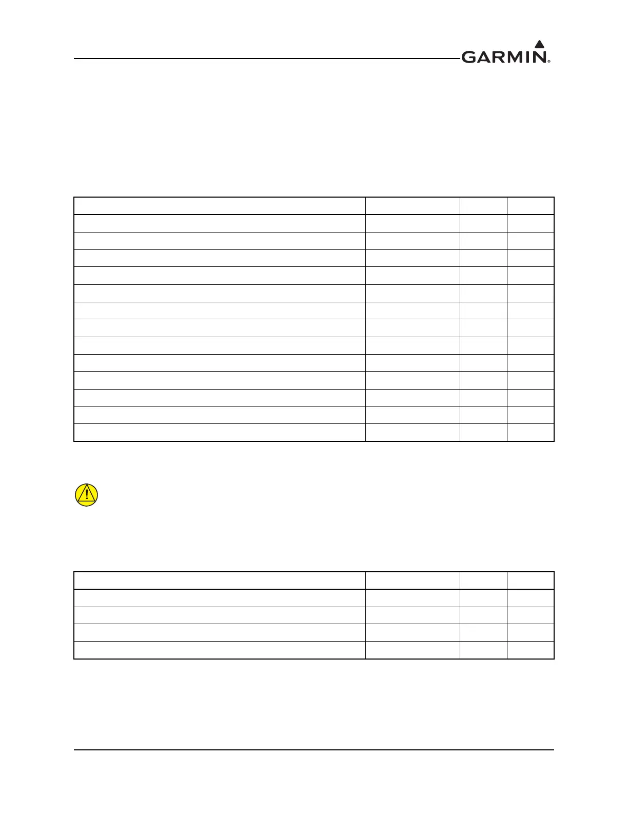
Pin Name Connector Pin I/O
AIRCRAFT POWER P2001 30 In
AIRCRAFT POWER P2001 43 In
AIRCRAFT POWER P2001 44 In
AIRCRAFT POWER P2002 51 In
AIRCRAFT POWER P2002 52 In
AIRCRAFT GROUND P2001 37 In
AIRCRAFT GROUND P2001 38 In
AIRCRAFT GROUND P2001 40 In
AIRCRAFT GROUND P2002 22 In
AIRCRAFT GROUND P2002 49 In
AIRCRAFT GROUND P2002 60 In
AIRCRAFT GROUND P2002 61 In
AIRCRAFT GROUND P2002 62 In
Pin Name Connector Pin I/O
LIGHTING HI 1 P2001 8 In
LIGHTING HI 2 P2001 2 In
LIGHTING LO 1 P2001 22 In
LIGHTING LO 2 P2001 32 In
 Loading...