3 Internal Frequency Converter Operation
3.1 General
This section is intended to provide an operational overview of the frequency converter’s main assemblies and circuitry. With this information, a repair technician
should have a better understanding of the frequency converter's operation and aid in the troubleshooting process.
3.2 Description of Operation
A frequency converter is an electronic controller that supplies a regulated amount of AC power to a three phase induction motor in order to control the speed of
the motor. By supplying variable frequency and voltage to the motor, the frequency converter controls the motor speed, or maintains a constant speed as the
load on the motor changes. The frequency converter can also stop and start a motor without the mechanical stress associated with a line start.
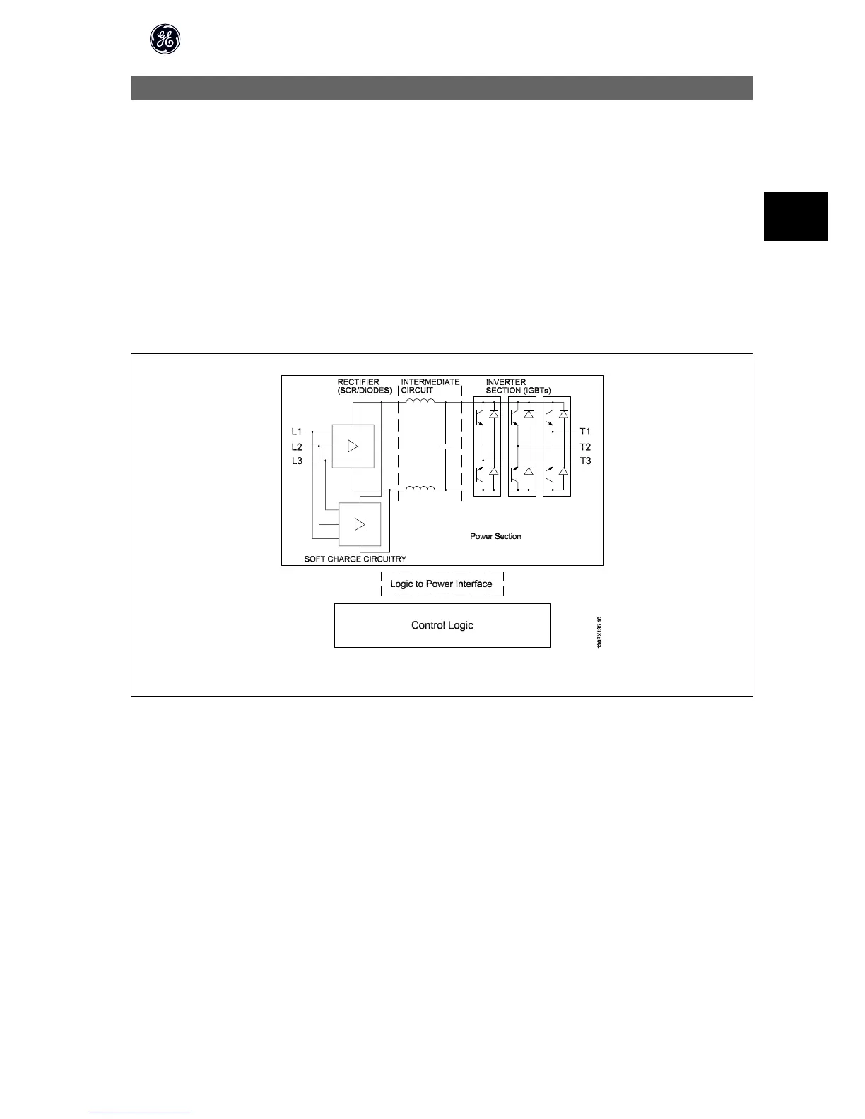
In its basic form, the frequency converter can be divided into four main sections: rectifier, intermediate circuit, inverter, and control (see illustration below).
Illustration 3.1: Control Card Logic
To provide an overview, the main frequency converter components will be grouped into three categories consisting of the control logic section, logic to power
interface, and power section. In the sequence of operation description, these three sections will be covered in greater detail while describing how power and
control signals move throughout the frequency converter.
High Power Service Manual for Unit Sizes 6x
31
3