6.2.2 Inverter Module Static Tests
The inverter module is primarily made up of the IGBTs used for switching the DC bus voltage to create the output to the motor. The IGBTs are grouped into three
per module. The frequency converter also has snubber capacitors on each IGBT module.
Before testing the inverter module, ohm check the top and bottom of the DC fuses to ensure no voltage is present. Dangerous and even fatal
voltage levels can be present if the capacitors are not fully discharged
Remove the safety covers to access the unit.
6.2.2.1 Test Point Access
To access test points in the module, remove the bus bars as follows.
1. If brake option is present, remove 2 brake option jumpers bus bars from each module by removing attaching nut on each end of bus bar.
2. Remove 3 motor jumper bus bars from each module by removing attaching nut on each end of bus bar.
3. Remove positive DC jumper bus bar from fuse by removing attaching hardware on each end of bus bar.
4. Remove negative DC jumper bus bar from fuse by removing attaching hardware on each end of bus bar.
1
2
3
4
2
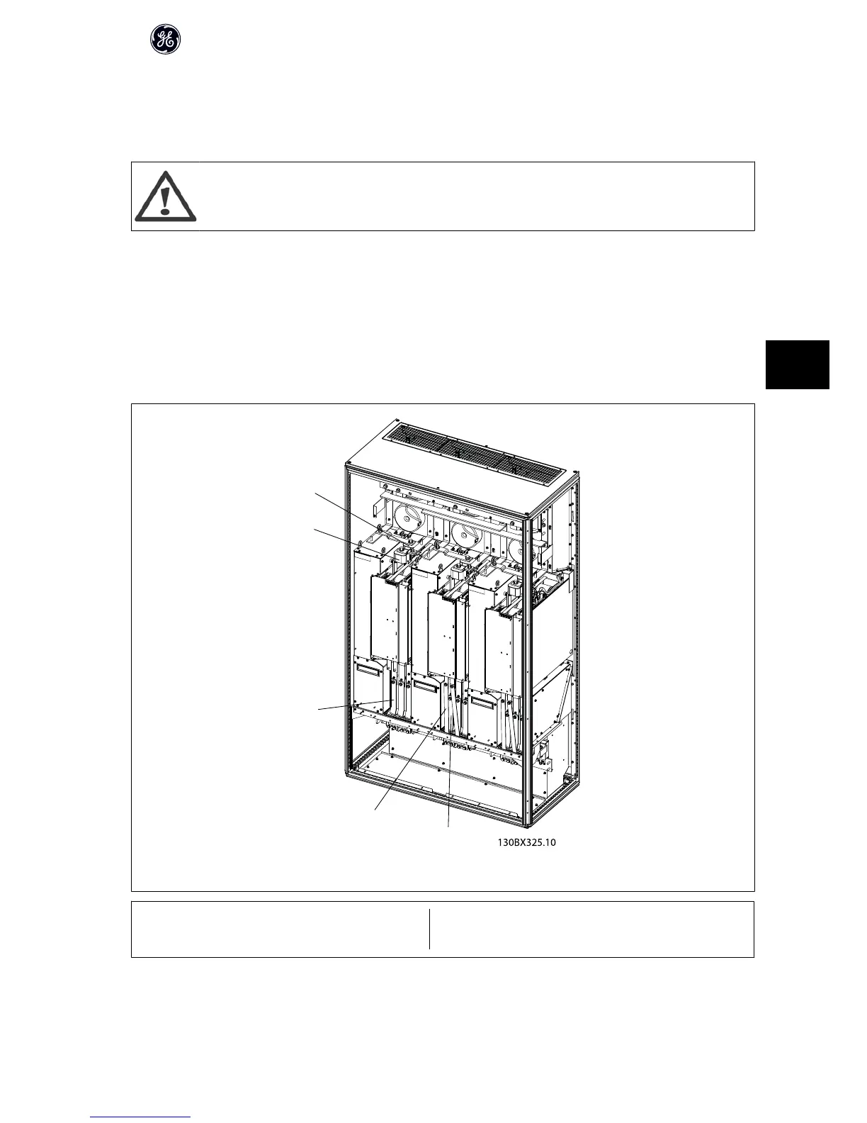
Illustration 6.2: Inverter module test points
1 Brake option jumper bus bar (step 1) 3 Negative (-)DC link fuse block
2 Motor jumper bus bar (step 2) 4 Positive (+)DC link fuse block
Before starting tests, ensure that meter is set to diode scale.
High Power Service Manual for Unit Sizes 6x
77
6
 Loading...


