Ports and flow paths of the Loop
valve
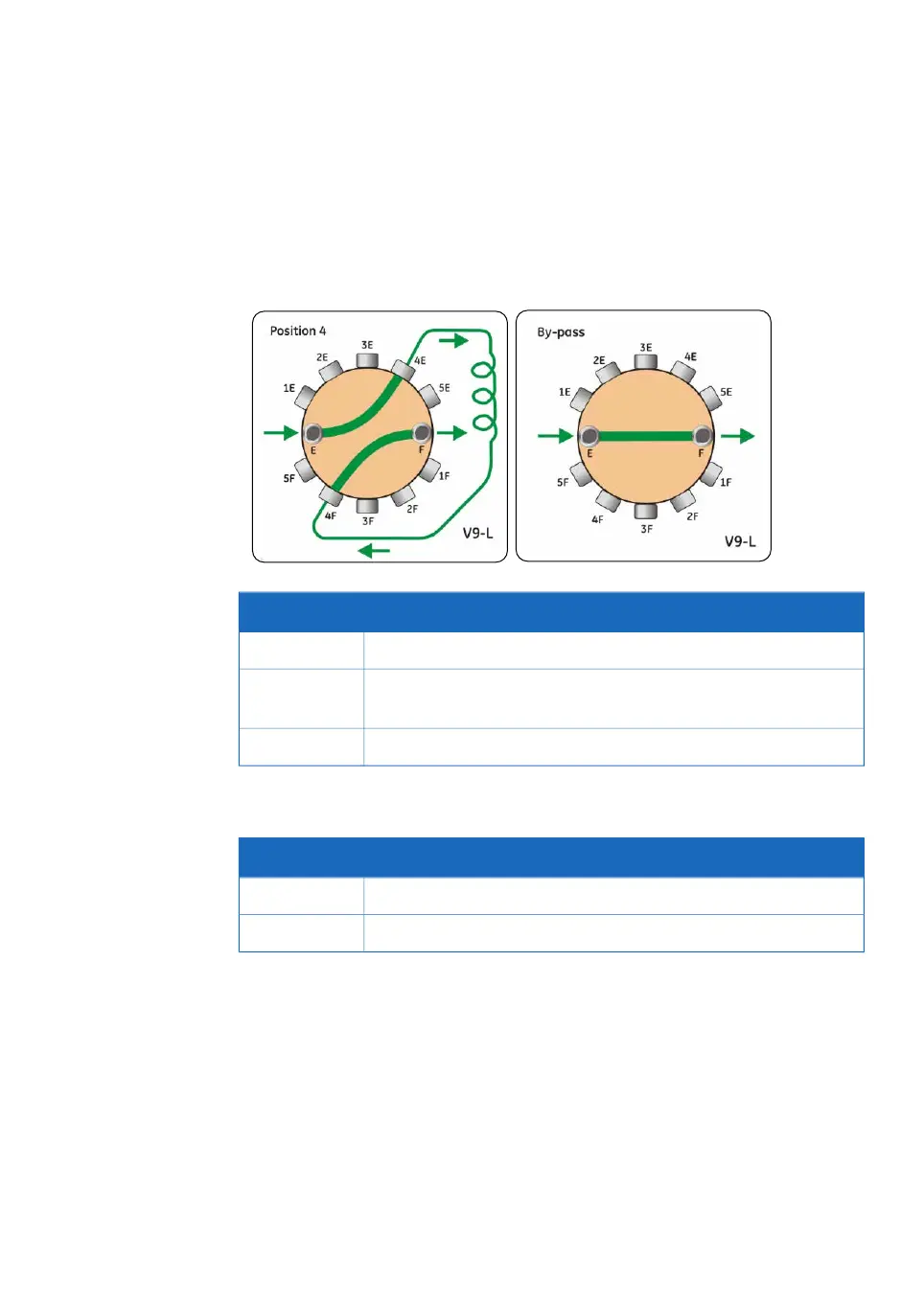
The illustration and tables below describe the ports and different flow paths through the
Loop valve. In the Position 4 example, the loop is connected to loop position 4 and the
loop is being emptied.
DescriptionPort
Port connected to the LoopF port of the Injection valve.F
Ports for connection of loop 1 to loop 5.1F and 1E to
5F and 5E
Port connected to the LoopE port of the Injection valve.E
Ports denoted by the letter F are used for filling the loop and ports denoted by
the letter E are used for emptying the loop.
Note:
DescriptionFlow path
The flow direction depends on the Injection valve position.Position 1-5
The flow by-passes the loop(s). By-pass is the default flow path.By-pass
ÄKTA avant User Manual 29035184 AE 125
4 Optional instrument modules
4.7 Loop valve

 Loading...