CHAPTER 5: SETTINGS OVERVIEW
B90 LOW IMPEDANCE BUS DIFFERENTIAL SYSTEM – INSTRUCTION MANUAL 5-3
5
5.2 Overview
5.2.1 Introduction to elements
For URs, the term element is used to describe a feature that is based around a comparator. The comparator is provided
with an input (or set of inputs) that is tested against a programmed setting (or group of settings) to determine if the input is
within the defined range that sets the output to logic 1, also referred to as setting the flag. A single comparator can make
multiple tests and provide multiple outputs. For example, the time overcurrent comparator sets a pickup flag when the
current input is above the setting and sets an operate flag when the input current has been at a level above the pickup
setting for the time specified by the time-current curve settings. All comparators use analog actual values as the input.
Elements are arranged into two classes, grouped and control. Each element classed as a grouped element is provided with
six alternate sets of settings, in setting groups numbered 1 through 6. The performance of a grouped element is defined by
the setting group that is active at a given time. The performance of a control element is independent of the selected active
setting group.
The main characteristics of an element are shown on a logic diagram. This includes the inputs, settings, fixed logic, and the
output operands generated. The previous chapter explains how to read a logic diagram, and the abbreviations used in a
diagram are defined in the Abbreviations chapter.
Some settings are specified in per-unit (pu) calculated quantities:
pu quantity = (actual quantity) / (base quantity)
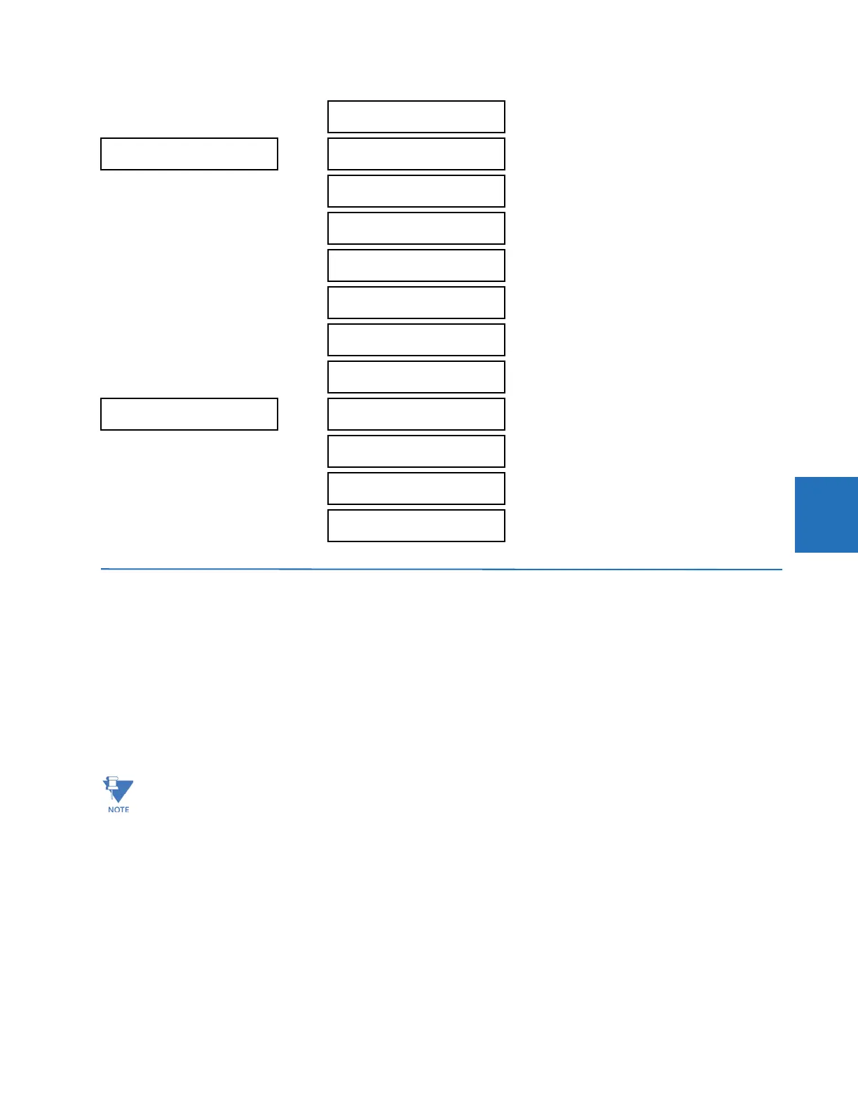
MONITORING
ELEMENTS
See page 5-185
SETTINGS
INPUTS / OUTPUTS
CONTACT INPUTS
See page 5-190
VIRTUAL INPUTS
See page 5-192
CONTACT OUTPUTS
See page 5-193
VIRTUAL OUTPUTS
See page 5-196
RESETTING
See page 5-196
DIRECT INPUTS
See page 5-197
DIRECT OUTPUTS
See page 5-197
SETTINGS
TESTING
TEST MODE
FUNCTION: Disabled
Range: Disabled, Isolated, Forcible
See page 5-201
TEST MODE FORCING:
On
Range: FlexLogic operand
See page 5-202
FORCE CONTACT
INPUTS
See page 5-202
FORCE CONTACT
OUTPUTS
See page 5-203
An exception to this rule is digital elements, which use logic states as inputs.
 Loading...


