9-4 B90 LOW IMPEDANCE BUS DIFFERENTIAL SYSTEM – INSTRUCTION MANUAL
DIFFERENTIAL PRINCIPLE CHAPTER 9: THEORY OF OPERATION
9
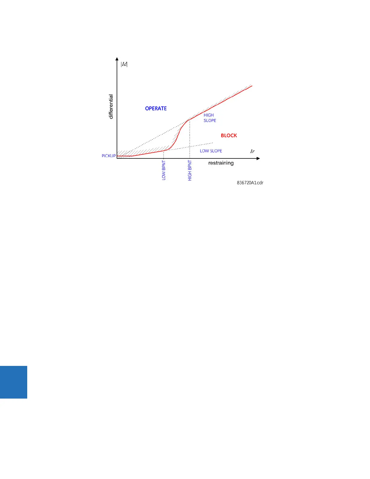
Figure 9-2: Biased operating characteristic
The higher slope used by the B90 acts as an actual percentage bias regardless of the value of the restraining signal. This is
so because the boundary of the operating characteristic in the higher slope region is a straight line intersecting the origin
of the ‘differential - restraining’ plane. The advantage of having a constant bias specified by the
HIGH SLOPE setting creates
an obstacle of a discontinuity between the first and second slopes. This is overcome by using a smooth approximation
(cubic spline) of the characteristic between the lower and higher breakpoints. Consequently, the characteristic ensures
• A constant percentage bias of
LOW SLOPE for restraining currents below the lower breakpoint of LOW BPNT,
• A constant percentage bias of
HIGH SLOPE for restraining currents above the higher breakpoint of HIGH BPNT, and
• A smooth transition from the bias of
LOW SLOPE to HIGH SLOPE between the breakpoints
9.3.2 Differential and restraining currents
The differential current is produced as a sum of the phasors of the input currents of a differential bus zone taking into
account the status signals of the currents, for example applying the dynamic bus replica of the protected zone. The
differential current is scaled to the maximum rated primary current. The scaling must be taken into account when setting
the
PICKUP value of the biased differential characteristic and the HIGH SET operating point of the unbiased differential
function.
The restraining current is produced as a maximum of the magnitudes of the phasors of the zone input currents taking into
account the status signals of the currents, for example applying the dynamic bus replica of the protected bus zone. The
restraining current is scaled to the maximum rated primary current. The scaling must be taken into account when setting
the breakpoints of the biased differential characteristic.
The “maximum of” definition of the restraining signal biases the relay toward dependability without jeopardizing security
as the relay uses additional means to cope with CT saturation on external faults. An additional benefit of this approach is
that the restraining signal always represents a physical — compared to an “average” or “sum of” — current flowing through
the CT that is most likely to saturate during given external fault. This brings more meaning to the breakpoint settings of the
operating characteristic.
The following example is provided with respect to the breakpoint settings.
9.3.2.1 Example 2
Proceed with the previous example and assume that taking into account the relevant factors such as properties of the CTs
themselves, resistance of the leads, and burden of the CTs, the following primary currents are guaranteed to be
transformed without significant saturation:
 Loading...


