9-10 B90 LOW IMPEDANCE BUS DIFFERENTIAL SYSTEM – INSTRUCTION MANUAL
OUTPUT LOGIC AND EXAMPLES CHAPTER 9: THEORY OF OPERATION
9
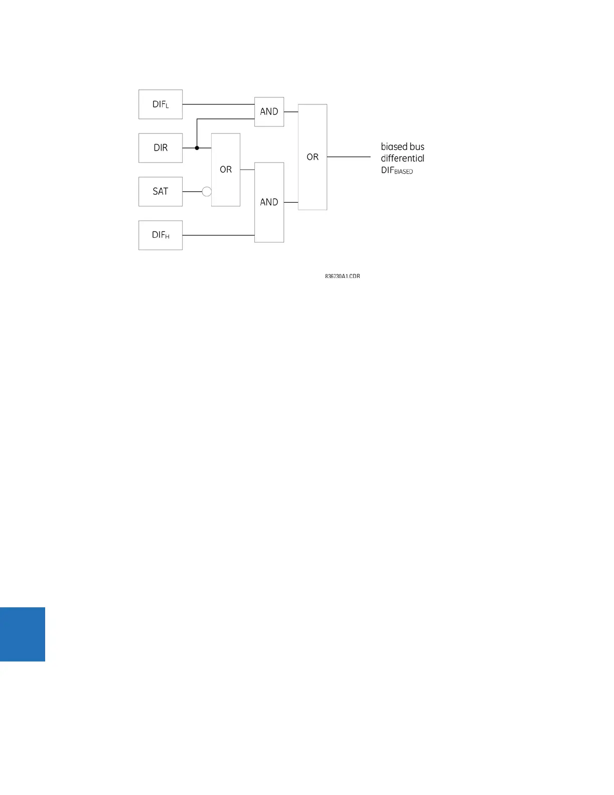
Figure 9-8: Output logic of biased differential protection
9.6.2 Internal and external fault example
Two examples of relay operation are presented: an external fault with heavy CT saturation and an internal fault.
The protected bus includes six circuits connected to CT terminals F1, F5, M1, M5, U1, and U5, respectively. The circuits F1,
F5, M1, M5, and U5 are capable of feeding some fault current; the U1 circuit supplies a load. The F1, F5, and U5 circuits are
significantly stronger than the F5 and M1 connections.
The M5 circuit contains the weakest (most prone to saturation) CT of the bus.
The first of the following figures presents the bus currents and the most important logic signals for the case of an external
fault. Despite very fast and severe CT saturation, the B90 remains stable.
The second figure presents the same signals but for the case of an internal fault. The B90 trips in 10 ms (fast form-C output
contact).