6-10 B90 LOW IMPEDANCE BUS DIFFERENTIAL SYSTEM – INSTRUCTION MANUAL
METERING CHAPTER 6: ACTUAL VALUES
6
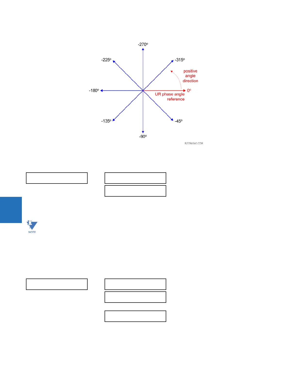
Figure 6-2: UR phase angle measurement convention
6.4.2 Bus zone
ACTUAL VALUES METERING BUS BUS ZONE 1(6)
These values display the differential and restraint currents phasors for each bus zone. The magnitudes are displayed in
primary amperes.
6.4.3 Currents
ACTUAL VALUES METERING CURRENTS
The metered current values for each terminal are displayed in this menu.
BUS ZONE 1
BUS ZONE 1 DIFF:
0.000 A 0.0°
BUS ZONE 1 REST:
0.000 A 0.0°
There is no cutoff level applied to the differential and restraint currents computed by the B90. Therefore, a small
differential current reflecting CT inaccuracies and bus leakage current can be present during balanced conditions.
This is done to achieve a more accurate differential balance and to provide a direct indication of the real differential
current, as excluding small currents or not accounting for CT errors can impose significant unaccounted
differential current. It is advisable to set the minimum pickup for 87B protection greater than the maximum
differential current during normal load conditions.
CURRENTS
F1 CURRENT:
0.000 A 0.0°
F2 CURRENT:
0.000 A 0.0°
S8 CURRENT:
0.000 A 0.0°
 Loading...


