5-106 B90 LOW IMPEDANCE BUS DIFFERENTIAL SYSTEM – INSTRUCTION MANUAL
PRODUCT SETUP CHAPTER 5: SETTINGS
5
Table 5-13: Oscillography cycles/record example
TRIGGER MODE — A new record automatically overwrites an older record when TRIGGER MODE is set to “Automatic
Overwrite.”
TRIGGER POSITION — Set this to a percentage of the total buffer size (for example, 10%, 50%, 75%, and so on). A trigger
position of 25% consists of 25% pre- and 75% post-trigger data.
TRIGGER SOURCE — Always captured in oscillography and can be any FlexLogic parameter (element state, contact input,
virtual output, and so on). The relay sampling rate is 64 samples per cycle.
AC INPUT WAVEFORMS — Determines the sampling rate at which AC input signals (that is, current and voltage) are stored.
Reducing the sampling rate allows longer records to be stored. This setting has no effect on the internal sampling rate of
the relay, which is always 64 samples per cycle. That is, it has no effect on the fundamental calculations of the device.
5.3.10.2 Digital channels
SETTINGS PRODUCT SETUP OSCILLOGRAPHY DIGITAL CHANNELS
DIGITAL 1(63) CHANNEL — This setting selects the FlexLogic operand state recorded in an oscillography trace. The length of
each oscillography trace depends in part on the number of parameters selected here. Parameters set to “Off” are ignored.
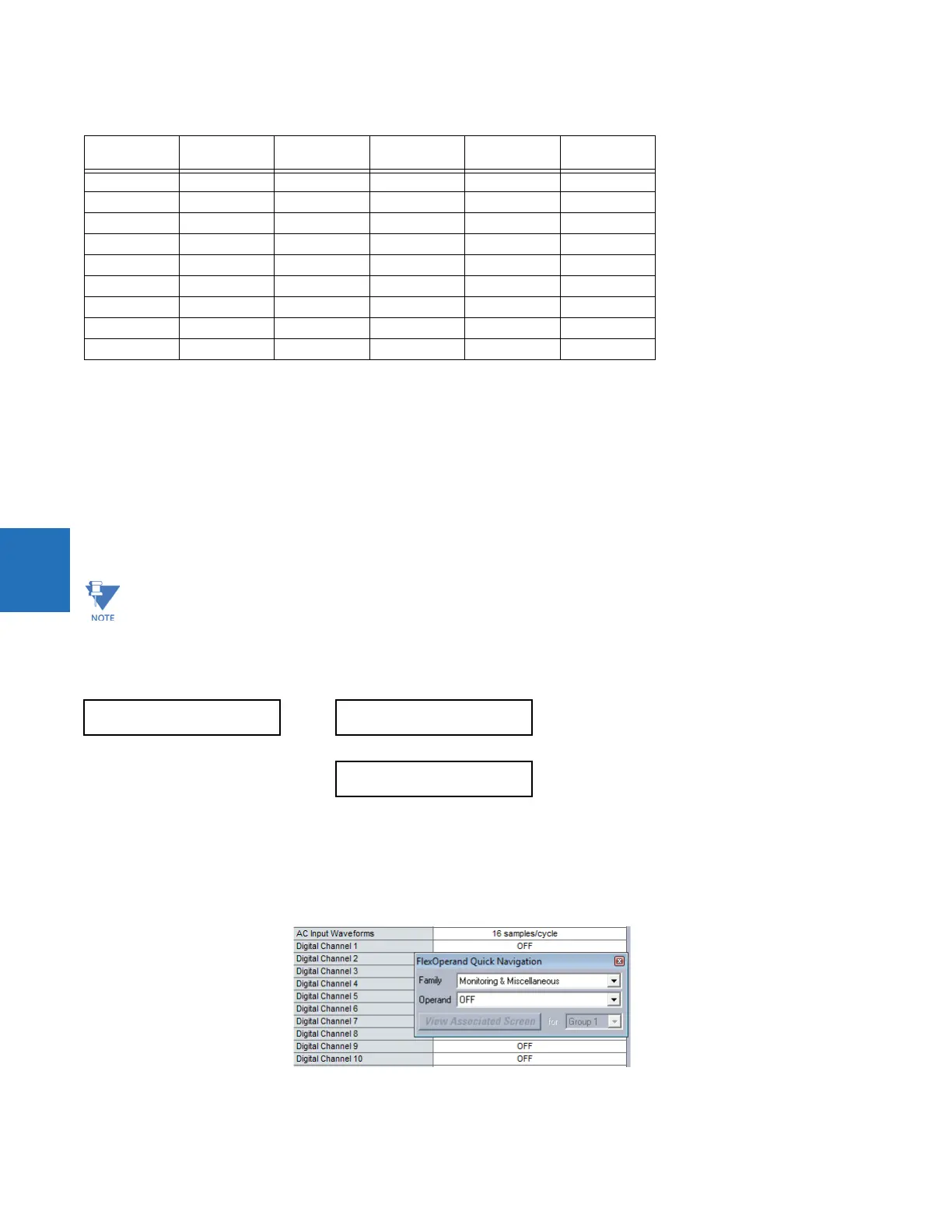
To populate quickly the rows in the Offline Window, use Ctrl C/V to copy/paste, or click then double-click a row to display a
quick selection window.
Figure 5-46: Quick selection window
Records CT/VTs Sample rate Digital
channels
Analog
channels
Cycles per
record
3 1 32 32 16 2399
3 1 64 32 16 1450
161 323216666
161 643216402
321 323216352
321 643216213
3 2 32 32 16 1516
3 2 64 32 16 851
162 323216421
When changes are made to the oscillography settings, all existing oscillography records are cleared.
DIGITAL CHANNELS
DIGITAL CHANNEL 1:
Off
Range: FlexLogic operand
DIGITAL CHANNEL 63:
Off
Range: FlexLogic operand
 Loading...


