10-22 B90 LOW IMPEDANCE BUS DIFFERENTIAL SYSTEM – INSTRUCTION MANUAL
REPLACE FRONT PANEL CHAPTER 10: MAINTENANCE
10
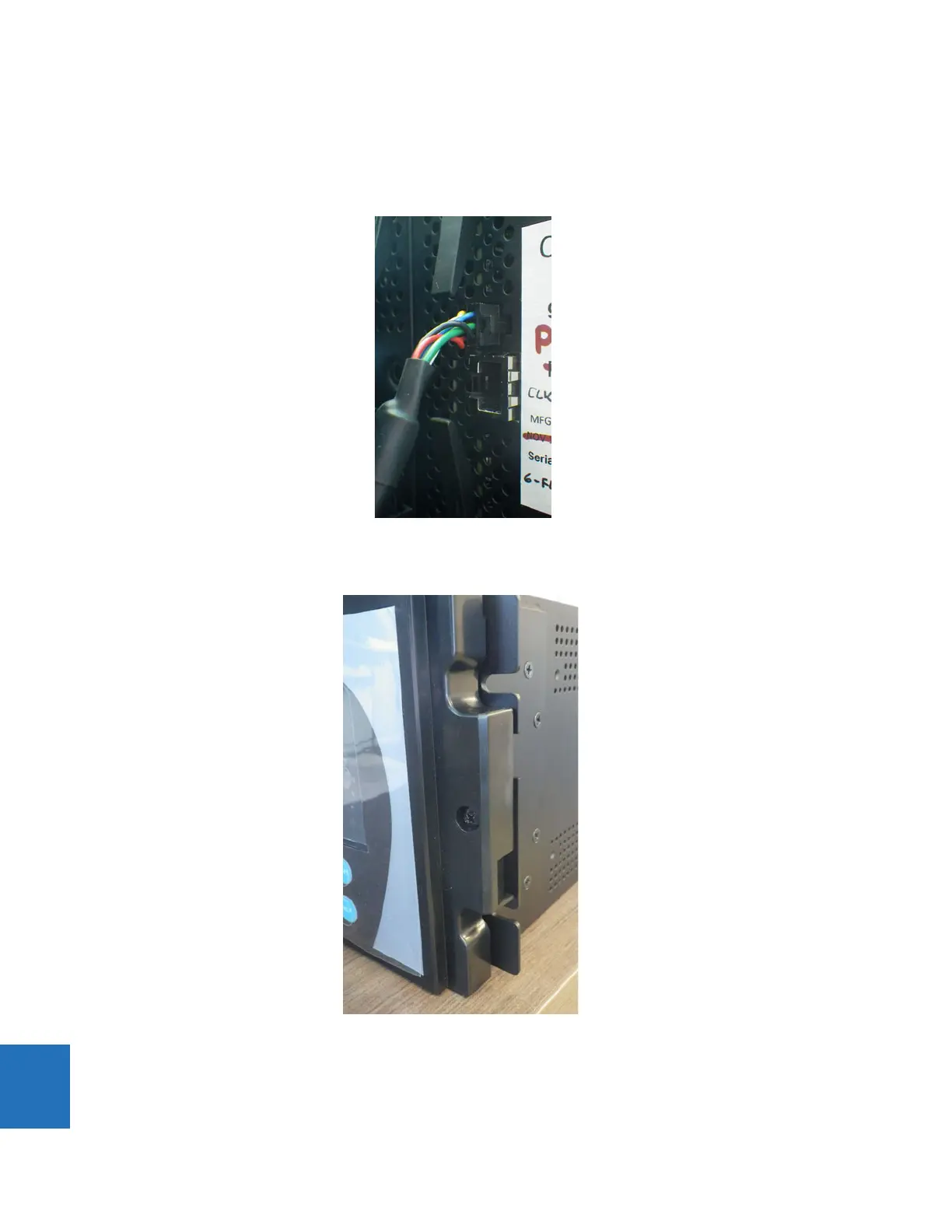
3. Once the module is in place, connect the graphical front panel to the CPU module (ground and upper connector) and
close the front panel. There are two connections possible on the front of the CPU module: upper for the graphical front
panel and lower for the enhanced and standard front panels. The upper connection is black with holes, similar to the
cover, so it is difficult to see.
Figure 10-24: Connect graphical front panel to top connection on CPU module
4. Tighten the embedded screw on the right side of the graphical front panel to the mounting bracket.
Figure 10-25: Screw to attach graphical front panel to mounting bracket
5. At the back of the CPU module, attach the new black cover plate to the back of the relay, then connect the new RS485
connector.
Insert the silver SFP connector(s) at the back of the CPU module, then connect any Ethernet connection(s).
6. Power up the relay. If the graphical front panel does not power up immediately, disconnect power, open the front
 Loading...


