OPM_LPS_33E_10K_30K_4CN_V010.doc 31/82 Operating Manual LP 33 / 10-20-30 kVA
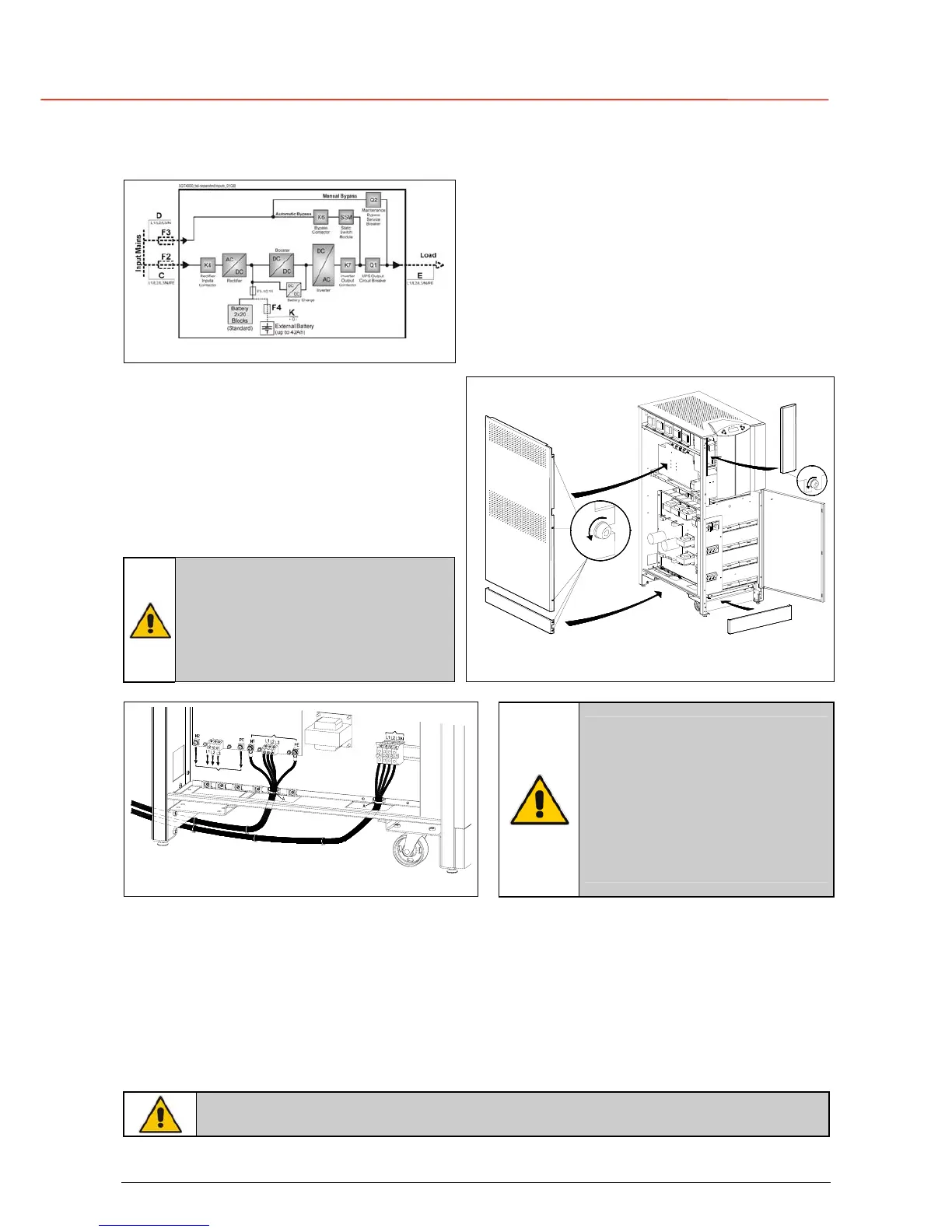
4.8.2 Separate input mains (option)
Fig. 4.8.2-1 Separate input mains (option)
Separate input mains
On request, the UPS can be delivered for
separate input mains.
Two independent lines (F2 and F3) supply
separately the rectifier and the bypass inputs
With this configuration, when the rectifier-input
fuses are opened, the automatic bypass and the
maintenance bypass are supplied by the other
line.
Access to the AC terminals
1 - Open the front door “A” of the cabinet.
2 - Remove the front panel “B”
loosening the screw “F”.
3 - Remove the front panel protection cover
“C” by pulling it off.
4 - Remove the left side panels “D and E”
loosening the screws “G”.
NOTE !
Neutral of rectifier input and
neutral of bypass input must be
coming from the same input bar.
Inside the UPS, neutrals N1 and
N are connected together.
SGT4000_010-020_UPS connection_02
A
B
C
D
E
G
F
Fig. 4.8.2-2 Power IN / OUT connections
SGT4000_010-020_connection separate_01IT
U
s
c
i
t
a
C
a
r
i
c
o
R
a
d
d
r
i
z
z
a
t
o
r
e
I
n
g
r
e
s
s
o
R
e
t
e
I
n
g
r
e
s
s
o
R
e
t
e
B
y
p
a
s
s
Fig. 4.8.1-3 Separated input mains
NOTE !
Input/output terminals must be
tightened with a proper
screwdriver applying torsion
force 1,2 / 1,4 Nm.
Clamp the input/output cables
with the included cable-ties
“A”.
Rectifier input mains connection
L1 = Phase L1 rectifier L2 = Phase L2 rectifier L3 = Phase L3 rectifier
N1 = Neutral mains PE = Earth
Bypass input mains connection
L1 = Phase L1 bypass L2 = Phase L2 bypass L3 = Phase L3 bypass
N = Neutral mains
Output load connection
L1 = Phase L1 load L2 = Phase L2 load L3 = Phase L2 load
N2 = Neutral load PE = Earth load
NOTE !
For UPS correct operation, the input mains phase rotation must be clock-wise.

 Loading...


