– 33 –
Understanding The Binary Chart
Explaining Binary Code
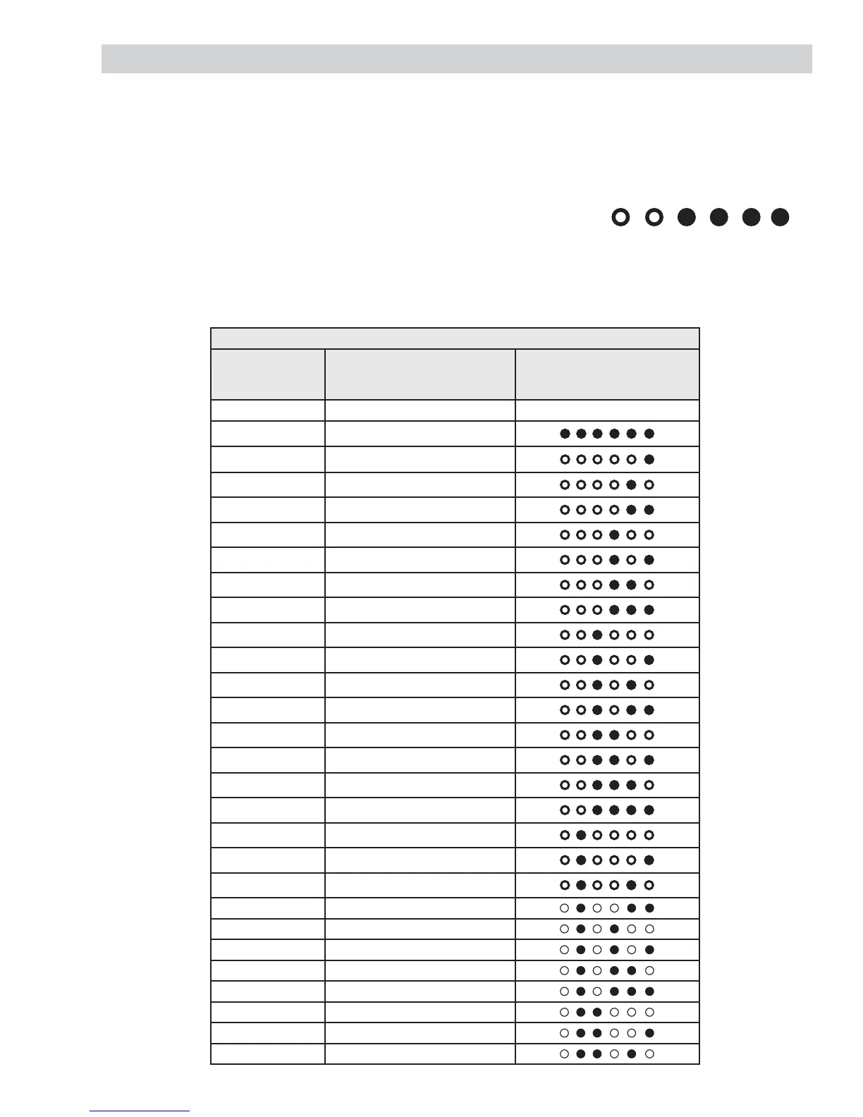
Binary codes are a series of LEDs that are lit and read from right to left. Each column has a number above
it and will double its value going from right to left as shown here. Lit LEDs will correspond with the number
in the far left column of the chart below. This is done by adding the numbers at the top of the column of the
cycle status LEDs that are lit.
Example7HVW*RLQJIURPULJKWWROHIWWKH¿UVWF\FOHVWDWXV/('VDUHOLW
Add the numbers of the lit LEDs together.
1 + 2 + 4 + 8 = 15
So it is in test 15
Binary Display Fault Chart
Fault/Test #
displayed on
7-segment display
When entered into service
mode
Fault/Test # displayed in
binary format using cycle
status lights
Service Mode Tests Filled circles indicate light on
0 All LEDs on
1 Fault Codes
2 Personality ID
3 UI Software Version (Critical)
4 UI Software Version (Non-critical)
5 XML Version (Non-critical)
6 Hot Water Valve
7 Cold Water Valve
8 Fabric Softener Dispenser
9 Spray Rinse Valve
10 Pressure Sensor
11 Recirculate Pump
12 Drain Pump
13 Lid Switch
14 Spin
15 Agitate
16 Clear all Fault Codes
17 Change Personality
18 Analog Knob
19
20
21
22
23
24
25
26
32 16 8 4 2 1
 Loading...