– 35 –
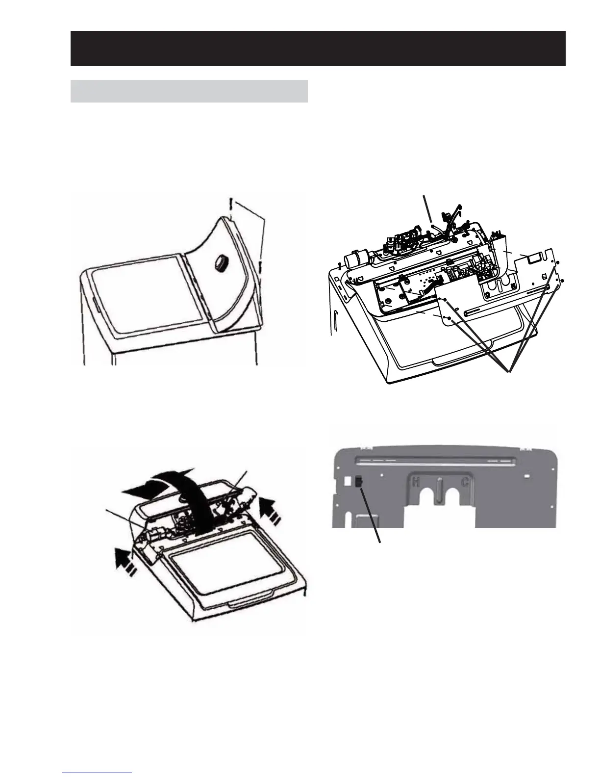
Before removing the backsplash assembly, be
sure to protect the lid and top cover with a towel
or material to keep the lid from being damaged.
1. Remove the two 1/4 in. hex head screws that
secure the backsplash to the top cover.
2. Grasp the backsplash sides, push it back.
Then rotate it toward the rear of the washer
so that the pressure tube can be seen and
disconnected from the pressure sensor,
mounted on the control board.
3. Carefully disconnect the pressure tube from
the control board. Twisting the pressure tube
ZKLOHSXOOLQJZLOOKHOSLWVOLSRႇRIWKHSUHVVXUH
sensor.
4. Rotate the backsplash assembly forward and
carefully lay it face down.
5. Remove the four 1/4 in. hex head screws that
secure the rear cover to the backsplash, and
OLIWLWRႇFDUHIXOO\7KHUHLVDJURXQGZLUHDQG
the RJ45 connector connected to the rear
cover that will need to be disconnected.
6. Disconnect the RJ45 connector by pressing
down on the release tab and push through the
opening.
When reinstalling the RJ45, the stationary lip
of the connector needs to be inserted into the
RSHQLQJ¿UVW
NOTE: Be sure to reconnect and test all ground
wires.
Backsplash
Screws
Pressure Sensor Tube
Capacitor
Pressure
Sensor
Tube
Four 1/4 in.
hex head
screws
RJ45
Connector
Cabinet and Structure
 Loading...