10 31-7000173 Rev. 0
Installation Instructions
D
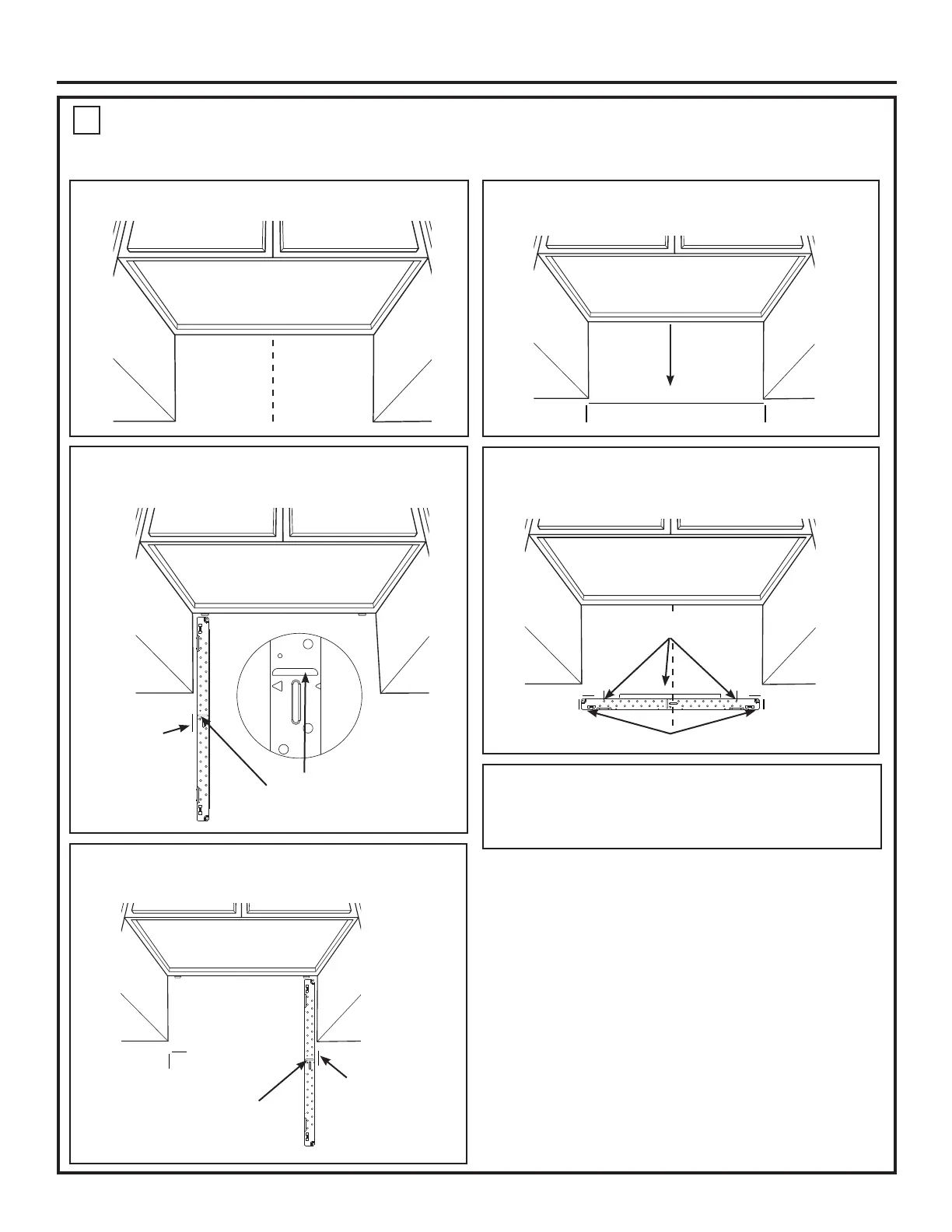
STEP 2: Installer uses bracket to make 2 marks. First
mark is made by using the stampled slot in bracket. Second
mark is made on the ouside edge of bracket.
STEP 1: Draw a vertical line on the wall at the center of
the 30” space.
STEP 4: Installer uses a level to draw a horizontal line
that connects the two marks made with the stamped slot in
the bracket.
STEP 5: Installer places the mounting bracket on the wall
as shown in the picture. Draw circles on the wall at holes A
and B. Draw at least one circle in area C. At least one circle
MUST line up with a wall stud.
STEP 6: Set mounting bracket aside and drill holes at
all marked locations. If there is a stud, drill a 3/16” hole for
wood screws. For holes that do not line up with a stud, drill a
5/8” hole for a toggle bolt.
Make a mark here, along inside
bottom of the stamped slot
provided.
Make a mark
here on the
outside edge
of the bracket
Horizontal line
NOTE: Refer to step C “DETERMINING MOUNTING PLATE LOCATION UNDER YOUR CABINET on page 8 for aligning instructions.
MARKING THE MOUNTING HOLES
OPTION 2: USE METAL BRACKET AS TEMPLATE
STEP 3: Installer moves bracket to the other side of the
cabinets and makes 2 more marks. Marks are the same as
STEP 2, just opposite side.
Make a mark here, along
inside bottom of the
stamped slot provided
(same as Step 1).
Make a mark
here on the
outside edge of
the bracket
A
C
B
Place bracket within the lines created in previous steps.
Mark hole locations for
A, B, and area C.

 Loading...