MA-001 – TRANSFIX-family Installation Manual – Rev 3.0 18-Jan-16 Page 20 of 55
8.3.1 Fitting Requirements
Figure 8—4 to Figure 8—6 shows the bottom plate connection points for each product.
The stainless steel tubing should be fitted between the transformer and the product as
follows, ensuring that:
The supply line is connected to the OIL IN port (this is the bulkhead fitting at the
bottom of the product that is located closest to the right-hand-side when viewed
from the front). This line will route to the transformer supply valve.
The return line is connected to the OIL OUT port (this is the bulkhead fitting at the
bottom of the product that is located closest to the left-hand side when viewed
from the front). This line will route to the Return Assembly on the transformer
valve.
All stainless steel tubing is clean and de-burred before attaching the tube fittings.
All tubing is properly secured to the transformer or other suitable non-vibrating
structures.
All tube fittings are sufficiently tight and tightened as per the fitting instructions
below (also outlined in the relevant Swagelok or Ham-Let documentation).
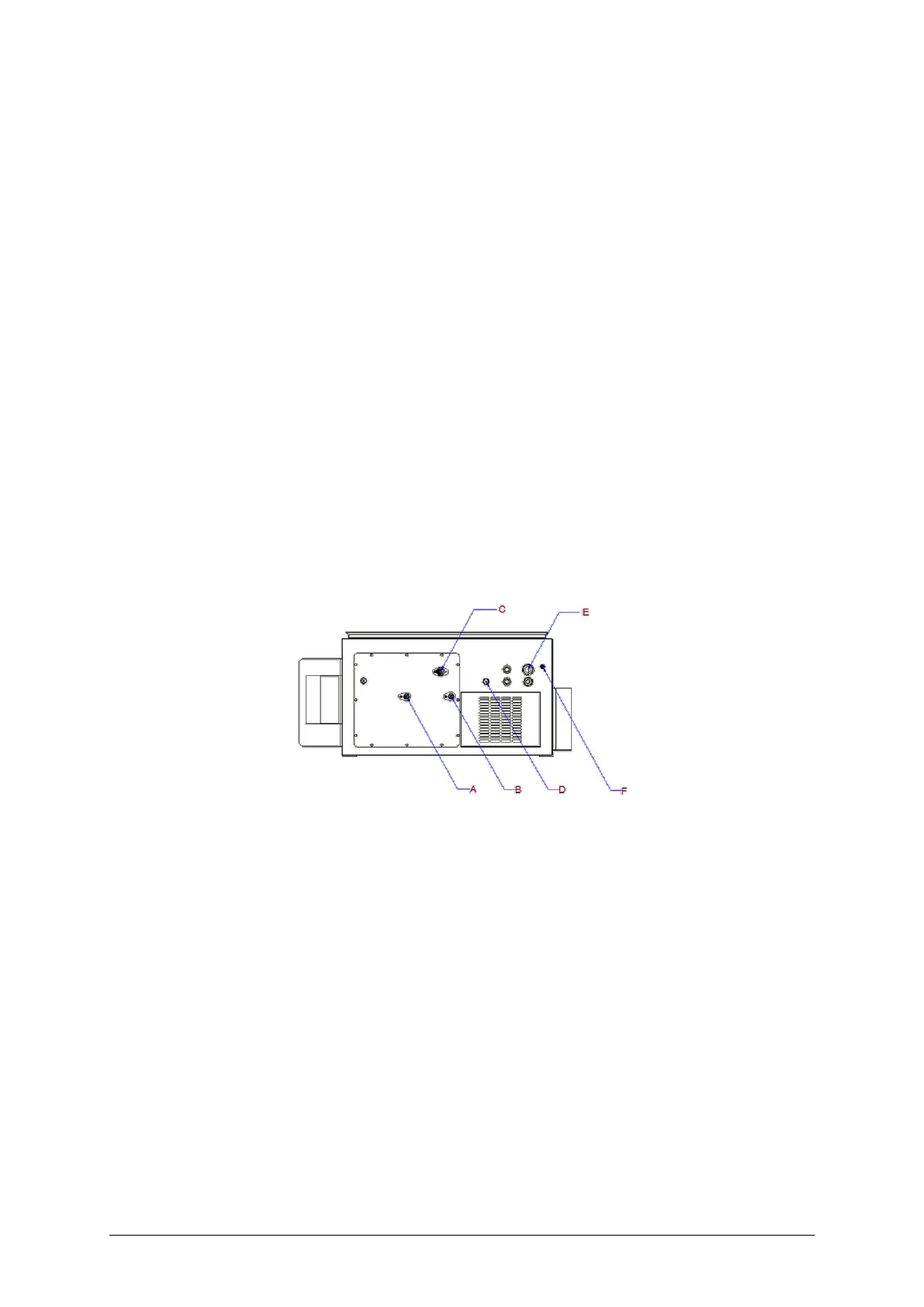
Figure 8—4: TRANSFIX 1.6 connections - bottom view
A. Oil-out D. Ambient temperature sensor
B. Oil-in E. Power-in (gland)
C. Manual sampling port F. M8 earth connection point

 Loading...


