MA-001 – TRANSFIX-family Installation Manual – Rev 3.0 18-Jan-16 Page 21 of 55
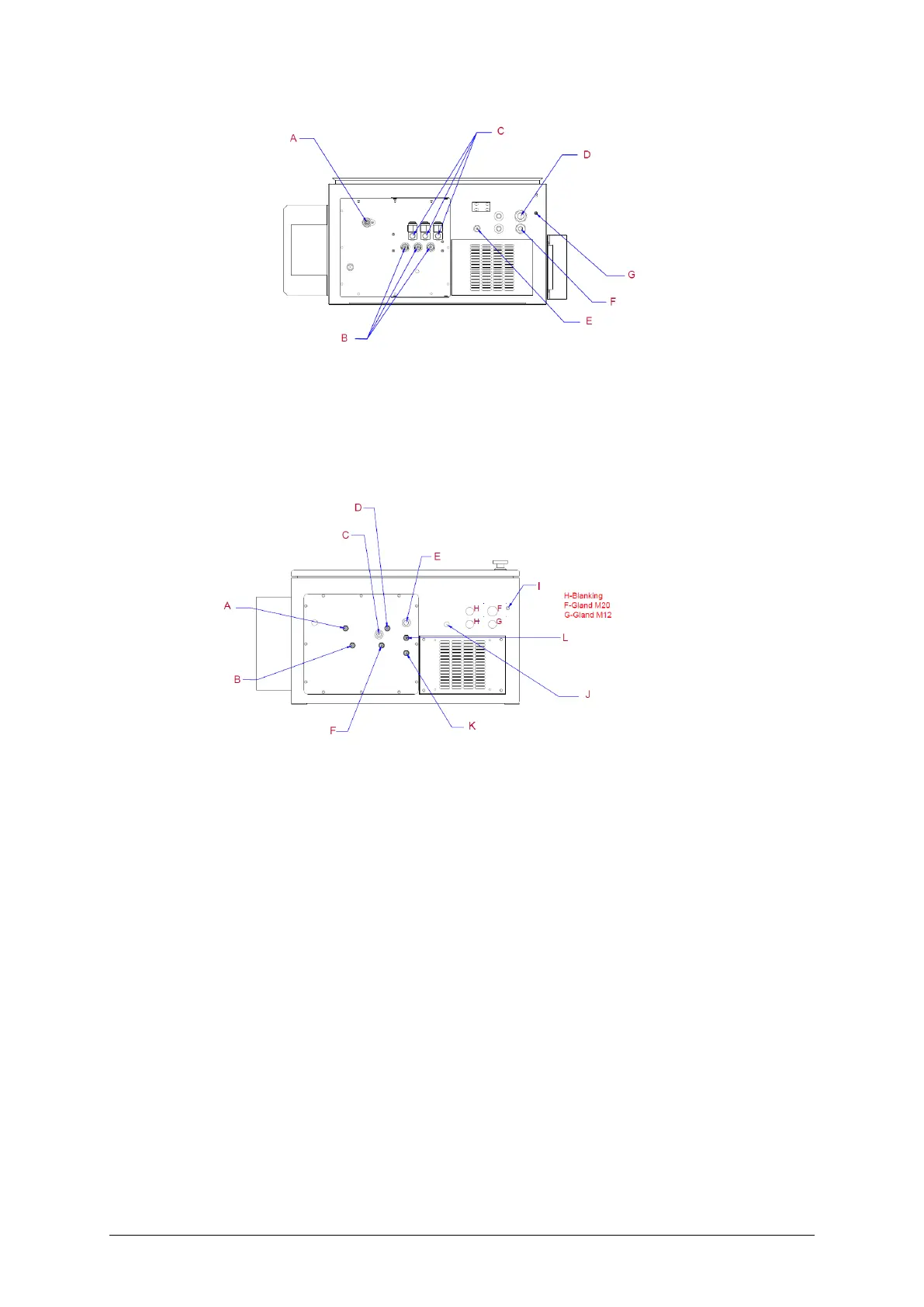
Figure 8—5: MULTITRANS connections - bottom view
Figure 8—6: TAPTRANS connections - bottom view
A. Manual sampling port E. Ambient temperature sensor
B. Oil-out ports (circuits 1, 2, 3) F. Communications cables gland
C. Oil-in ports (circuits 1, 2, 3) with filters G. M8 earth connection point
D Power cable gland
A. Out “C” selector F. In “A” main
B. Out “A” main I. M8 earth connection point
C. Manual DGA “A/C” J. Ambient temperature sensor
D. In “C” selector K. Out “B” diverter
E. Manual DGA “B” L. In “B” diverter

 Loading...


