GE Power Management MDP Digital Time Overcurrent Relay 3-
1
GEK-100682D 3 CONSTRUCTION
3
3 CONSTRUCTION 3.1 DESCRIPTION
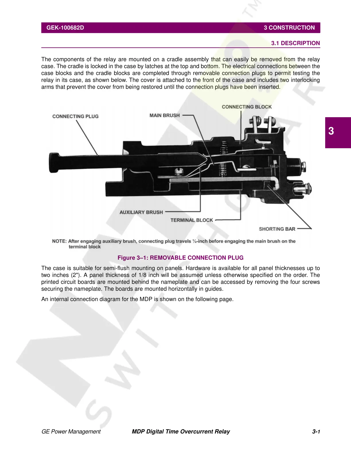
The components of the relay are mounted on a cradle assembly that can easily be removed from the relay
case. The cradle is locked in the case by latches at the top and bottom. The electrical connections between the
case blocks and the cradle blocks are completed through removable connection plugs to permit testing the
relay in its case, as shown below. The cover is attached to the front of the case and includes two interlocking
arms that prevent the cover from being restored until the connection plugs have been inserted.
Figure 3–1: REMOVABLE CONNECTION PLUG
The case is suitable for semi-flush mounting on panels. Hardware is available for all panel thicknesses up to
two inches (2"). A panel thickness of 1/8 inch will be assumed unless otherwise specified on the order. The
printed circuit boards are mounted behind the nameplate and can be accessed by removing the four screws
securing the nameplate. The boards are mounted horizontally in guides.
An internal connection diagram for the MDP is shown on the following page.
Courtesy of NationalSwitchgear.com
 Loading...


