GE Power Management MDP Digital Time Overcurrent Relay 1-
1
GEK-100682D 1 INTRODUCTION
1
1 INTRODUCTION 1.1 PRODUCT DESCRIPTION
The MDP Digital Time Overcurrent Relay is a digital, microprocessor based, nondirectional overcurrent relay
that protects against phase-to-phase and phase-to-ground faults. The MDP™ performs the following functions:
• Inverse overcurrent, including four characteristic curves and four values of definite time protection, as well
as instantaneous overcurrent protection with programmable delay
• Phase and ground current measurement
• Phase and ground current metering
• Operating time and fault current of the last trip
• Breaker status
• Breaker operation (RS232 and RS485 versions only)
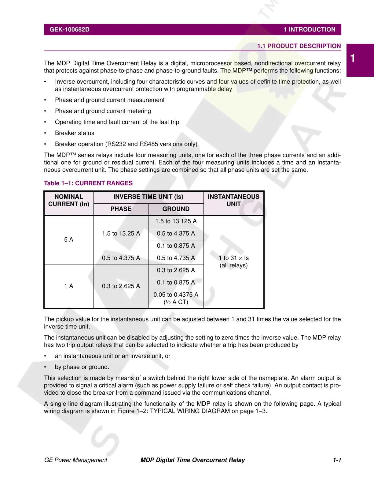
The MDP™ series relays include four measuring units, one for each of the three phase currents and an addi-
tional one for ground or residual current. Each of the four measuring units includes a time and an instanta-
neous overcurrent unit. The phase settings are combined so that all phase units are set the same.
The pickup value for the instantaneous unit can be adjusted between 1 and 31 times the value selected for the
inverse time unit.
The instantaneous unit can be disabled by adjusting the setting to zero times the inverse value. The MDP relay
has two trip output relays that can be selected to indicate whether a trip has been produced by
• an instantaneous unit or an inverse unit, or
• by phase or ground.
This selection is made by means of a switch behind the right lower side of the nameplate. An alarm output is
provided to signal a critical alarm (such as power supply failure or self check failure). An output contact is pro-
vided to close the breaker from a command issued via the communications channel.
A single-line diagram illustrating the functionality of the MDP relay is shown on the following page. A typical
wiring diagram is shown in Figure 1–2: TYPICAL WIRING DIAGRAM on page 1–3.
Table 1–1: CURRENT RANGES
NOMINAL
CURRENT (In)
INVERSE TIME UNIT (Is) INSTANTANEOUS
UNIT
PHASE GROUND
5 A
1.5 to 13.25 A
1.5 to 13.125 A
1 to 31
×
Is
(all relays)
0.5 to 4.375 A
0.1 to 0.875 A
0.5 to 4.375 A 0.5 to 4.735 A
1 A 0.3 to 2.625 A
0.3 to 2.625 A
0.1 to 0.875 A
0.05 to 0.4375 A
(½ A CT)
Courtesy of NationalSwitchgear.com
 Loading...


