GE Power Management MDP Digital Time Overcurrent Relay 7-
3
GEK-100682D 7 MODBUS PROTOCOL
7
7.4 MODBUS MEMORY MAP
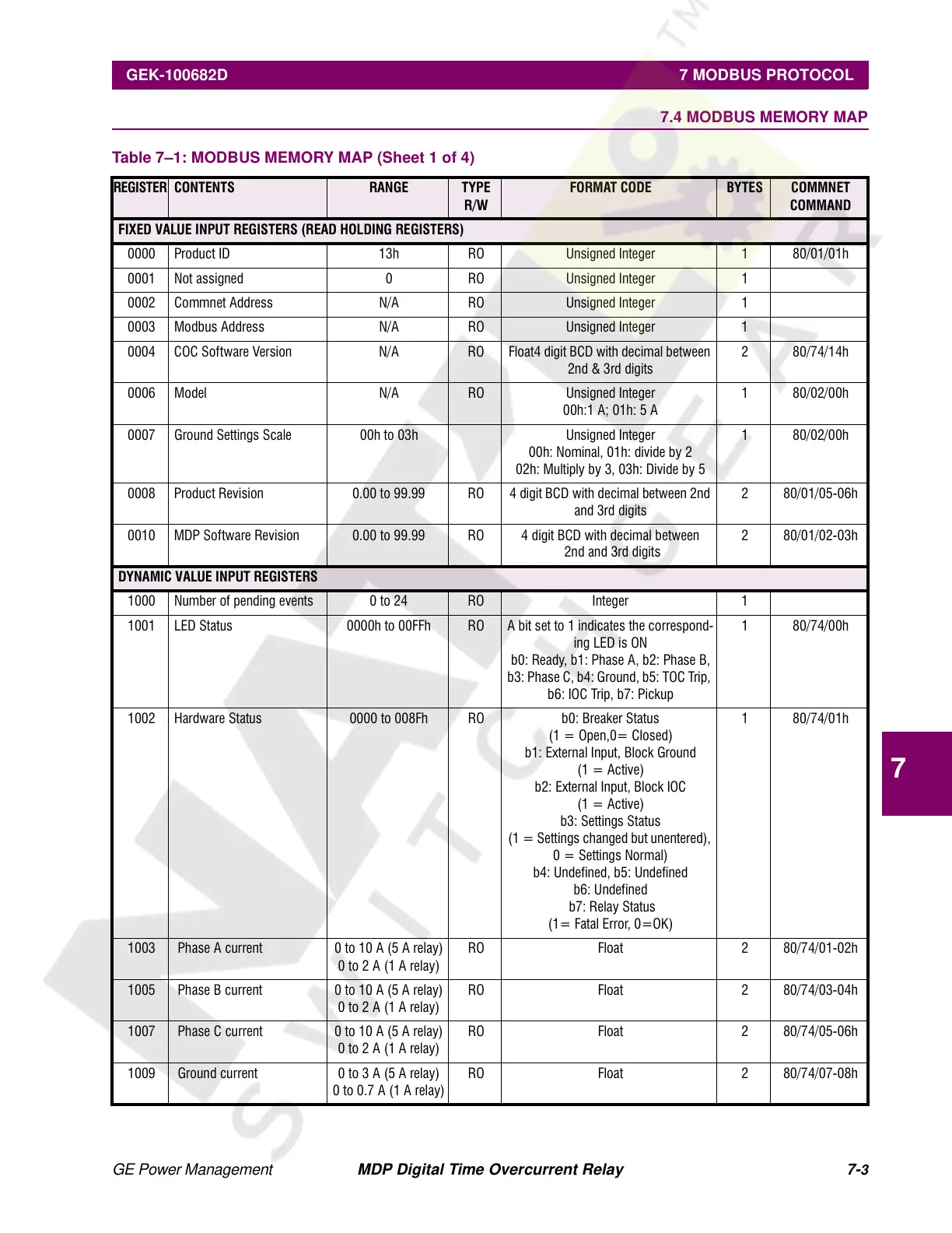
Table 7–1: MODBUS MEMORY MAP (Sheet 1 of 4)
REGISTER
CONTENTS RANGE TYPE
R/W
FORMAT CODE BYTES COMMNET
COMMAND
FIXED VALUE INPUT REGISTERS (READ HOLDING REGISTERS)
0000 Product ID 13h RO Unsigned Integer 1 80/01/01h
0001 Not assigned 0 RO Unsigned Integer 1
0002 Commnet Address N/A RO Unsigned Integer 1
0003 Modbus Address N/A RO Unsigned Integer 1
0004 COC Software Version N/A RO Float4 digit BCD with decimal between
2nd & 3rd digits
2 80/74/14h
0006 Model N/A RO Unsigned Integer
00h:1 A; 01h: 5 A
1 80/02/00h
0007 Ground Settings Scale 00h to 03h Unsigned Integer
00h: Nominal, 01h: divide by 2
02h: Multiply by 3, 03h: Divide by 5
1 80/02/00h
0008 Product Revision 0.00 to 99.99 RO 4 digit BCD with decimal between 2nd
and 3rd digits
2 80/01/05-06h
0010 MDP Software Revision 0.00 to 99.99 RO 4 digit BCD with decimal between
2nd and 3rd digits
2 80/01/02-03h
DYNAMIC VALUE INPUT REGISTERS
1000 Number of pending events 0 to 24 RO Integer 1
1001 LED Status 0000h to 00FFh RO A bit set to 1 indicates the correspond-
ing LED is ON
b0: Ready, b1: Phase A, b2: Phase B,
b3: Phase C, b4: Ground, b5: TOC Trip,
b6: IOC Trip, b7: Pickup
1 80/74/00h
1002 Hardware Status 0000 to 008Fh RO b0: Breaker Status
(1 = Open,0= Closed)
b1: External Input, Block Ground
(1 = Active)
b2: External Input, Block IOC
(1 = Active)
b3: Settings Status
(1 = Settings changed but unentered),
0 = Settings Normal)
b4: Undefined, b5: Undefined
b6: Undefined
b7: Relay Status
(1= Fatal Error, 0=OK)
1 80/74/01h
1003 Phase A current 0 to 10 A (5 A relay)
0 to 2 A (1 A relay)
RO Float 2 80/74/01-02h
1005 Phase B current 0 to 10 A (5 A relay)
0 to 2 A (1 A relay)
RO Float 2 80/74/03-04h
1007 Phase C current 0 to 10 A (5 A relay)
0 to 2 A (1 A relay)
RO Float 2 80/74/05-06h
1009 Ground current 0 to 3 A (5 A relay)
0 to 0.7 A (1 A relay)
RO Float 2 80/74/07-08h
Courtesy of NationalSwitchgear.com
 Loading...


