© 2010 by General Electric Company. All rights reserved. 2049809-001 Rev B 15
Chapter3 :Mini Telemetry Components
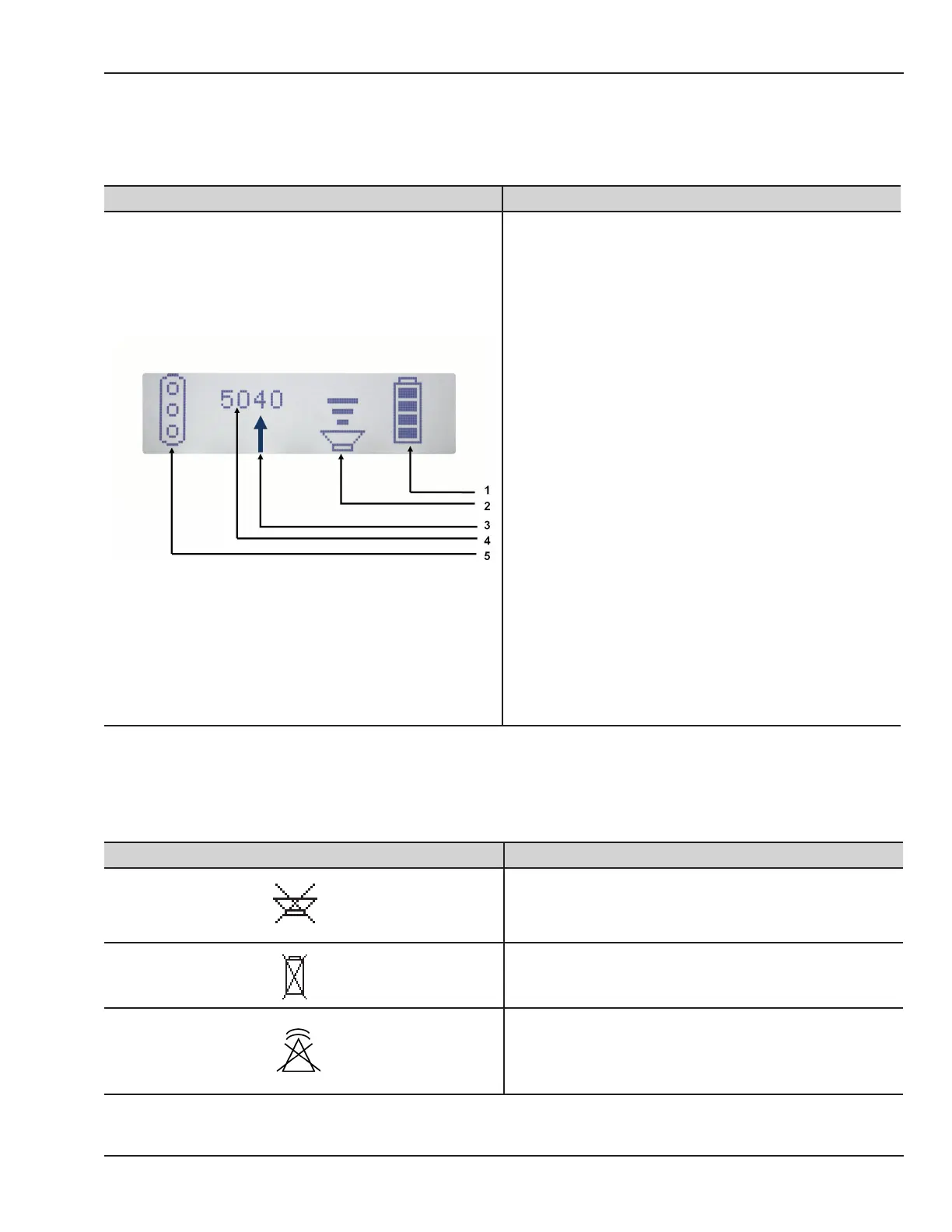
Display GUI
The following table describes the Transmitter display GUI:
Figure Description
1. Battery Charge Status:
Indicates battery level and charge status. Indications
continuously move while the battery is being charged.
2. Speaker Volume Status:
5 levels of volume and mute are indicated.
3. Mark Indicator:
Arrow mark is visible for an additional second after the
Mark key is released.
4. Channel Number:
Channel number of the transmitter is displayed. Refer
to the frequency chart in the service manual.
5. Transducer Connection Status:
Indicates the connection status of the parametric
connectors. Filled circle indicates connector plugged
in, empty circle indicates connector not plugged in.
Display Indications
The following table shows the transmitter display indications:
Indication Description
Indicates speaker is mute.
Indicates battery error.
Indicates radio module error.