© 2010 by General Electric Company. All rights reserved. 2049809-001 Rev B 31
Chapter4: Installation and Setup
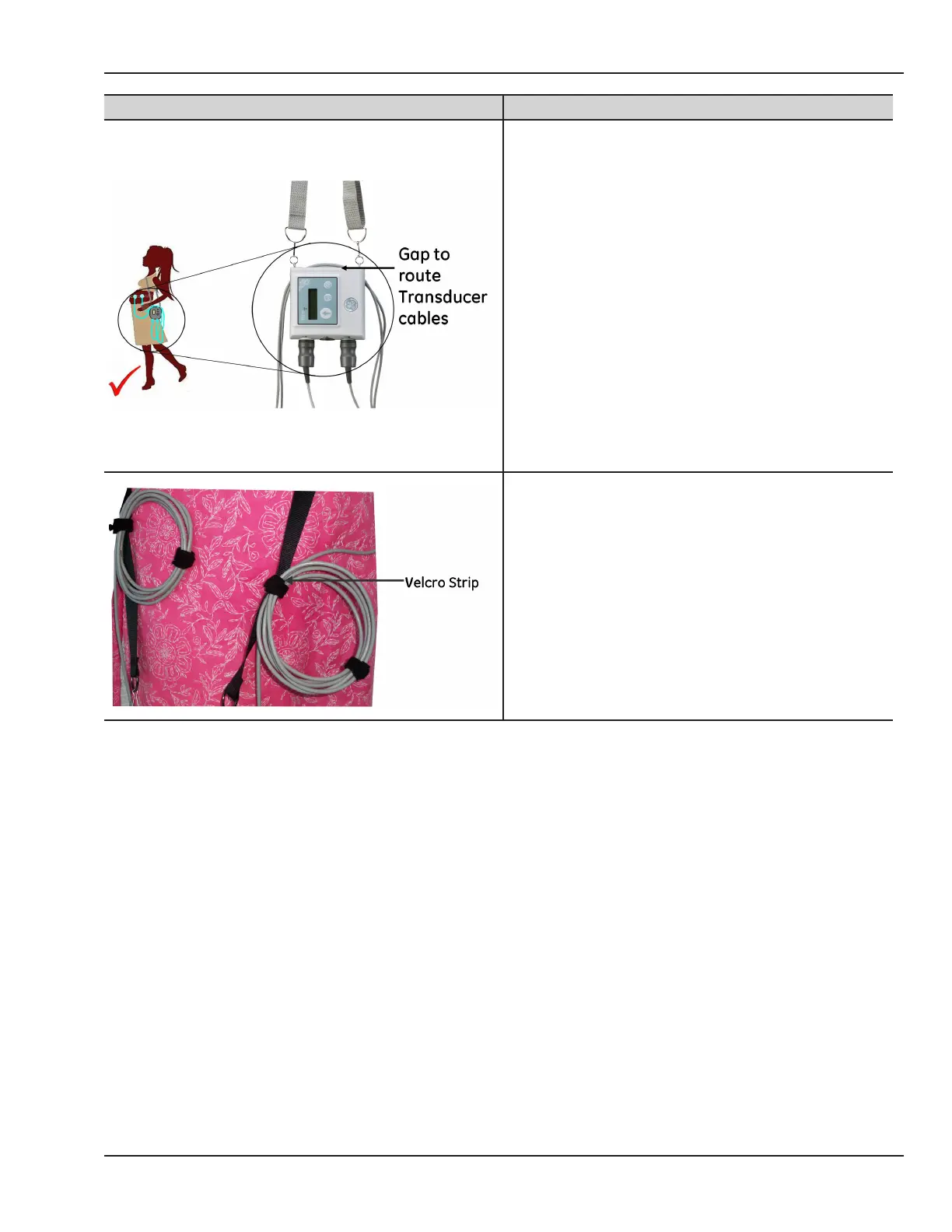
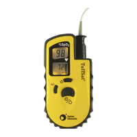
Illustration Description
2. Shorten the length of the transducer cables by
winding it around the transmitter as seen in the
gure to avoid tripping.
3. For additional transducer cable management
use the velcro strips provided to arrest the
transducer cables as shown in the gure.
Monitoring Reminders
General
• Use the correct interconnection method according to your monitor model. See page 19.
• Remember to apply power to all three devices: monitor, receiver and transmitter.
• Check that each interconnection cable is rmly attached to both the receiver and the monitor.
• As soon as any telemetry mode is detected, the front panel of the 250 or 170 Series Monitor is disabled
and all front panel inputs are ignored. In other words, telemetry and monitor modes cannot be “mixed and
matched”, you must use telemetry only or direct monitoring only.
IMPORTANT :
170 SERIES—For proper operation with a 170 Series Monitor, disconnect all transducers from the front panel of
the monitor.