CHAPTER 1: OVERVIEW MIN AND MIN II RELAYS
3 SERIES RETROFIT – INSTRUCTION MANUAL 11
1.5 MIN and MIN II relays
Most MIN and MIN II features are available in 350 relays as described in the table below:
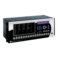
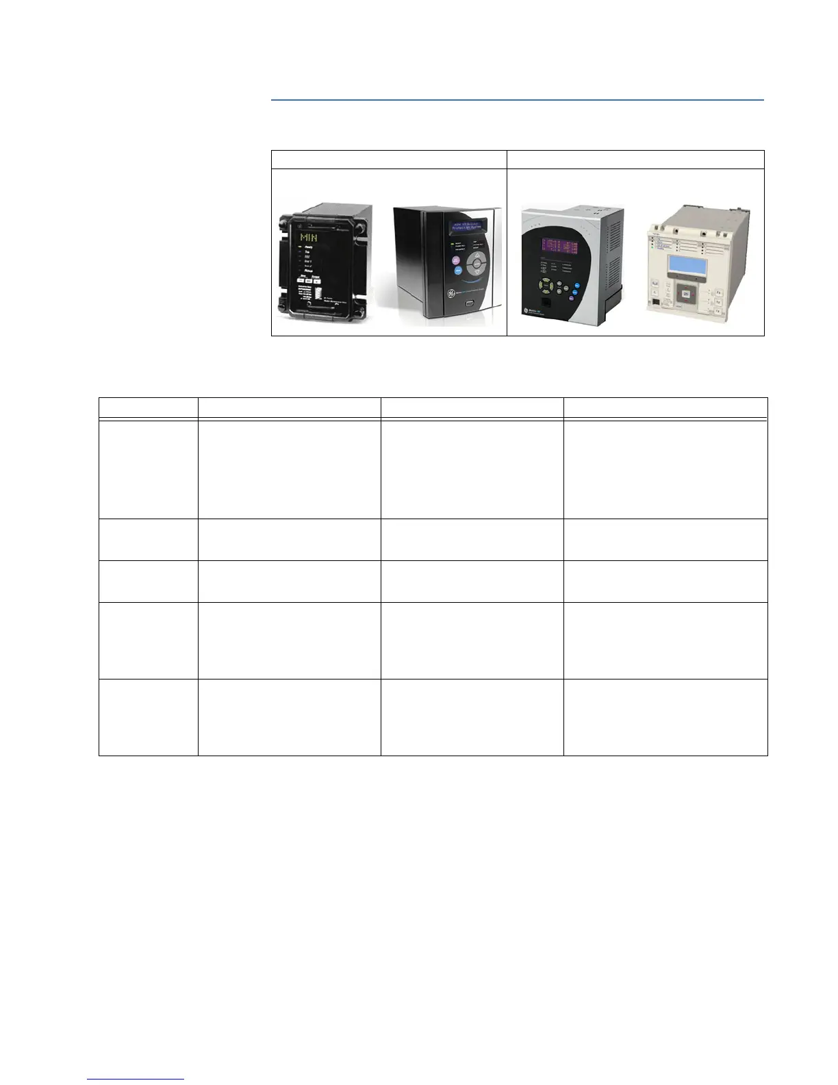
Installed Relay Retrofit Relay
MIN II Ground Protection System
MIN Digital Ground Protection
350 Feeder Protection System,
or P40 Agile Relay
Feature MIN
MIN II
1
350
2
Protection &
Control
Directional: 67N1, 67N2
IOC: 50GH, 50GL
TOC: 51GH, 51GL
Cold Load Pickup: CLP
Breaker Failure: 50BF
67G1, 67G2, 67PC1, 67PC2
50G1, 50G2
51G1, 51G2
Directional: 67P(1), 67N(1), 67G/SG(1)
IOC: 50P(2), 50N(2), 50_2, 50G/SG(2)
TOC: 51P(1), 51G/SG(1), 51N(1)
Cold Load Pickup: CLP
Breaker Failure: 50BF
Other: 49, 32N(2), VTFF + Voltage,
Power, and Energy Metering, 60CTS
Metering &
Monitoring
Metering
Breaker Health
Event Recording
Metering
Event Recorder
Metering
Breaker Health
Event Recording
Oscillography 8 samples/cycle
maximum length 24 cycles
8 samples/cycle
maximum length 24 cycles
up to 32 samples per cycle
(user-selectable)
maximum length 192 cycles
Communications Serial (RS232, RS485)
protocols: Modbus RTU
Serial (RS232, RS485)
protocols: Modbus RTU
USB
Serial (RS485) protocols: Modbus RTU,
DNP 3.0, IEC 60870-5-103
Ethernet protocols: Modbus TCP/IP,
DNP 3.0, IEC 60870-5-104, IEC 61850
GOOSE, IEC 61850, OPC-UA
Hardware 2 digital outputs
6 relay outputs
Configurable I/O
Configurable Logic
2 fixed LEDs
4 configurable LEDs
2 digital inputs
6 digital outputs
Configurable I/O
Configurable Logic
2 fixed LEDs
4 configurable LEDs
10 inputs
7 outputs (2 Form A, 5 Form C)
Configurable I/O
Configurable Logic
10 LEDs (non-programmable LEDs)
12 LEDs (programmable LEDs)
1. For a detailed example of converting the MIN II Option "S" 67IG1 function to the 350 32N function, see Converting MIN II 67IG1 to 350
32N on page 29.
2. For additional features, refer to the 350 Instruction Manual.

 Loading...