62 3 SERIES RETROFIT – INSTRUCTION MANUAL
239 WIRING CHAPTER 4: ELECTRICAL INSTALLATION
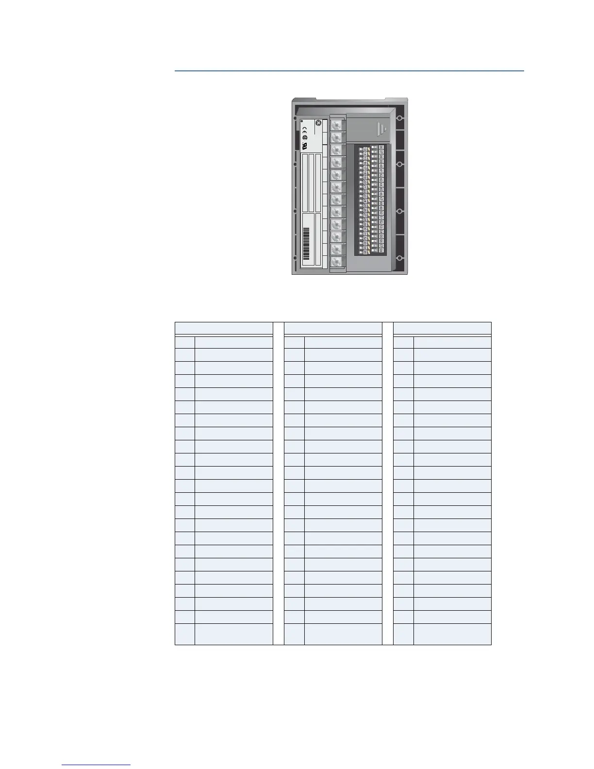
4.7 239 Wiring
Table 4–18: 239 Terminal Blocks
CT ROW SIGNAL LOWER ROW SIGNAL UPPER ROW
1 Phase A CT 5A 13 Safety ground* 36 Control live (+)
2 Phase A CT 1A 14 Filter ground 37 Control neutral (–)
3 Phase A CT COM 15 RS485 A+ 38 Sw com
4 Phase B CT 5A 16 RS485 B– 39 Sw com
5 Phase B CT 1A 17 RS485 ground 40 Sw com
6 Phase B CT COM 18 Analog out + 41 Sw com
7 Phase C CT 5A 19 Analog out – 42 Sw com
8 Phase C CT 1A 20 Analog out shield 43 Access sw +
9 Phase C CT COM 21 Thermistor in + 44 Restart sw +
10 Ground CT 5A 22 Thermistor com 45 Reset sw +
11 Ground CT 50:0.025 23 Trip NO 46 Option 1 sw +
12 Ground CT COM 24 Trip COM 47 Option 2 sw +
25 Trip NC 48 RTD shield
26 Alarm NO 49 RTD1 hot
27 Alarm COM 50 RTD1 comp
28 Alarm NC 51 RTD1 ret
29 Auxiliary NO 52 RTD2 hot
30 Auxiliary COM 53 RTD2 comp
31 Auxiliary NC 54 RTD2 ret
32 Service NO 55 RTD3 hot
33 Service COM 56 RTD3 comp
34 Service NC 57 RTD3 ret
35 V1 polarizing
(Mod 509 only)
58 Vcom polarizing
(Mod 509 only)
819790AG.CDR
110.000
SUPPLY VOLTAGE
TAG#
MOD#
®
NRTL
MAXIMUM CONTACT RATING
250 VAC 10A RESISTIVE
1/4 HP 125VAC 1/2HP 250VAC
12
11
10
9
8
7
654
3
2
1
MAXIMUM CONTACT RATING
250 VAC 10A RESISTIVE
1/4HP 125VAC 1/2HP 250VAC
MODEL
SUPPLY VOLTAGE SERIAL NO.:
TAG# 1234-567-89
90-300VDC 20VA
70-265VAC 50/60HZ 20VA
D6401234
239-RTD-AN
MADE IN CANADA
MOD#s NONE
FIRMWARE
64D240C4.000
GE Power Management

 Loading...