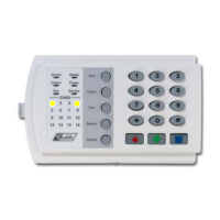
NX-4 Control
Page 14
LOCATION 6 - PROGRAMMING PHONE #2 (20 segments, numerical data)
Phone #2 is programmed in location 6. A "14" indicates the end of the phone number. Delays of four seconds can be
programmed at any point in the phone number by programming a "13" in the appropriate segment. If tone dialing is
desired, program a "15" in the segment where tone dialing should begin. If the entire number should be tone dialing,
program a "15" in the first segment. Program an A11" for a Ar@, and a A12" for a A#@. Caution: A call-waiting cancel
on a non- call waiting line will prevent successful connection to the central station.
LOCATION 7 - ACCOUNT CODE FOR THE PHONE #2 (6 segments of numerical data)
The account code sent when Phone #2 is dialed is programmed in location 7. Program a A10" in the segment
immediately after the last digit of the account code. If the account code is 6 digits long, program all 6 segments. If
this location is left unprogrammed, account code 1 will be used when the second phone number is dialed.
LOCATION 8 - COMMUNICATOR FORMAT FOR PHONE # 2 (1 segment, numerical data)
Location 8 contains the communicator format used to transmit to the receiver connected to Phone #2. Consult the
instruction manual for your central station receiver to determine which format is compatible, and select from the 15
formats listed on page 13. If you require a format other than those listed, review the override options described in
Location 18 to build the appropriate format. A "15" must be programmed in location 8 in addition to the entries in
location 18 in order to create a special format. If this location contains a "0", format 1 will be used when Phone #2 is
dialed.
LOCATION 9 - DIAL ATTEMPTS/BACKUP CONTROL FOR PHONE #2 (2 segments, numerical data)
Segment 1, Dial attempts: Segment 1 of Location 9 is used to enter the number of dial attempts (1 to 15 attempts)
the communicator will make to Phone #2 before ending the notification process. Factory default is "8" and the
communicator will make the same number of attempts as those programmed in location 3.
Segment 2, Phone #2 Backup Control: Programming a "0" in Segment 2 of this location will cause the NX-4 to
make the designated number of attempts to Phone #1 before setting the "Fail To Communicate" condition and stop
reporting. Programming a "1" in this segment will cause the NX-4 to stop trying to communicate after the designated
number of attempts have been made to Phone #2. If a "2" is programmed in this segment, it will cause the NX-4 to
make the dial attempts in increments of two. The first two attempts will be made to Phone #2, the next two attempts
to Phone #1, then repeating until the total number of attempts designated in Segment 1 is completed.
REPORTING EVENTS TO PHONE NUMBER 2
Phone #2 can be used to back up Phone #1 or for a second receiver to multi-report or split report events. Location 10
is used to select which events are reported to Phone #2. If dual or split reporting is not desired, location 10 should be
left at the factory default of "0". If multi-reporting or split reporting is desired, location 10 should be used to select
only those events that should be reported to Phone #2. If no events should be reported to Phone #2, location 10
should be "0".
LOCATION 10 - EVENTS REPORTED TO PHONE #2 (2 segments of feature selection data)
Segment 1: 1 = Alarms and Alarm Restores.
2 = Opening and Closings.
3 = Zone Bypass and Bypass Restores.
4 = Zone Trouble and Trouble Restores.
5 = Power Fail, Low Battery, Power Restore, and Low Battery Restore.
6 = Bell Cut, Bell Cut Restore.
7 = Test Reports.
8 = Start and End programming, Download complete.
Segment 2: 1 = Zone and Box Tamper and Tamper Restore.
2 = Auxiliary Power Over-current and Restore.
3 = Sensor Missing and Restore.
4 = Sensor Low Battery and Restore.
5 = Expander Trouble and Restore.
6 = Fail To Communicate.
7 = Reserved.
8 = Reserved.
 Loading...
