NX-4 Control
Page 37
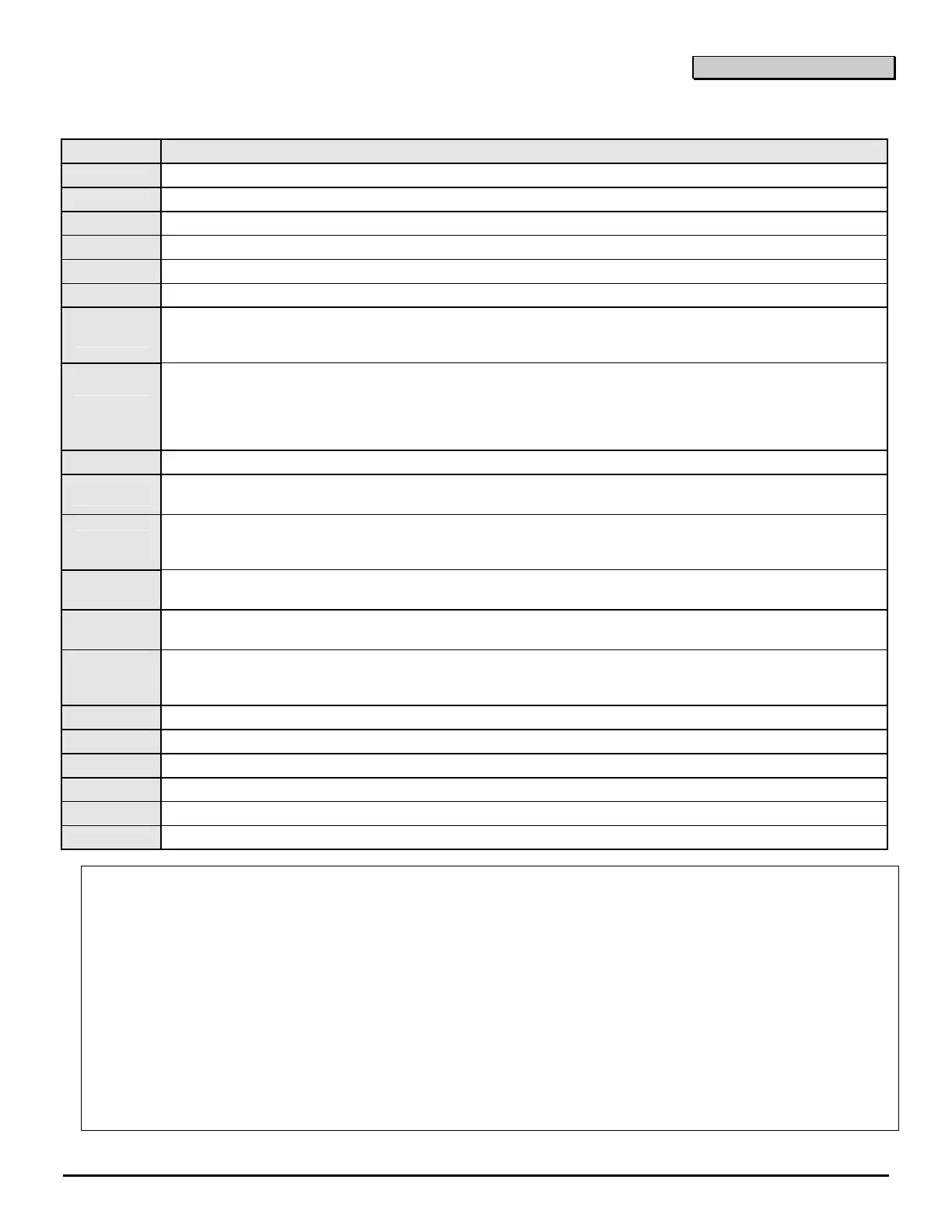
TERMINAL DESCRIPTIONS
TERMINAL
DESCRIPTION
R1
House Telephone Ring (Grey).
R
Telephone Ring (Red).
T
Telephone Tip (Green).
T1
House Telephone Tip (Brown).
AC
AC input. Connect to a 16.5V 25, 40 or 50 VA Class ll U.L. approved transformer.
EARTH
Earth Ground. Connect to a cold water pipe or a 6 to 10 foot driven rod.
AUX 1
Connect negative lead of low current device [relay, LED (install 1K Ω resistor in series with LED), etc.].
Connect positive lead of device to KEYPAD +. Current is limited to 250mA when output is negative, and
250FA when output is positive.
SIREN
If used as a siren output (default), the speaker rating should be 15 watt at 8 or 16 ohm, or 30/40 watt
at 4, 8, or 16 ohms. If voltage output is selected in location 37, this output becomes voltage output,
12VDC, 1 Amp maximum load. NOTE: A 3.3K Ω resistor may be required across the bell terminals
when a 12 VDC siren is used. If no resistor is used, you may experience voltage leakage into
the siren, which will cause these devices to output a small signal.
COM
Connect negative wire of siren/speaker or voltage output devices.
SMOKE+
Smoke detector power 12VDC, 250 mA maximum (For those jurisdictions which allow the Priority zone
to be used with smoke detectors.)
AUX 2
Connect negative lead of low current device [relay, LED (install 1K Ω resistor in series with LED), etc.].
Connect positive lead of device to KEYPAD +. Current is limited to 250mA when output is negative, and
250FA when output is positive.
KEYPAD
DATA
Connect to the data terminal on the keypads and the expanders. MAXIMUM: 8 keypads + 1 other device.
COM
AUX PWR -
Connect to the Common terminal on the keypads, expanders, and other power devices.
POS
AUX PWR
+
Connect to the Positive terminal on the keypads, expanders, and other power devices. This terminal is
limited to 1 amp total current.
ZONE 4
Connect to one side of zone 4 loop. Connect the other side to com terminal. Open or short causes alarm.
COM
Common (-) terminal for zones 3 & 4.
ZONE 3
Connect to one side of zone 3 loop. Connect the other side to com terminal. Open or short causes alarm.
ZONE 2
Connect to one side of zone 2 loop. Connect the other side to com terminal. Open or short causes alarm.
COM
Common (-) terminal for zones 1 & 2.
ZONE 1
Connect to one side of zone 1 loop. Connect the other side to com terminal. Open or short causes alarm.
K
IMPORTANT!
1. If separate power supplies are necessary to accommodate additional devices, safety standards require that each
power supply be prominently marked with adequate instructions for removing all power from the unit.
2. Dispose of used batteries according to the manufacturer’s instructions and/or local government authorities.
3. Installation personnel should thoroughly read and understand the installation instructions and the users manuals
for the panel and all the accessories to be included with the system before attempting to install a security
system.
WARNING!
Replace only with Panasonic #LC12V4BP or Yuasa #NP4-12 battery. Observe polarity when installing a new battery.
Installing the battery backwards may cause damage to the panel. There is a risk of explosion if the battery is replaced
with an incorrect type.
NOTE
Electrical codes will vary depending upon the country and city where the system is installed. It is the installer’s
responsibility to ensure that the electrical installation is safe and conforms to all applicable codes, laws, or regulations.
Only qualified persons should connect this device to the mains supply.

 Loading...


