Page
BOARD INSTALLATION
Inside the can, several 2-holed insertion points have been constructed. This allows for
either vertical or horizontal placement of the modules. Notice that each insertion point has
two sizes of holes B a larger hole and a smaller hole.
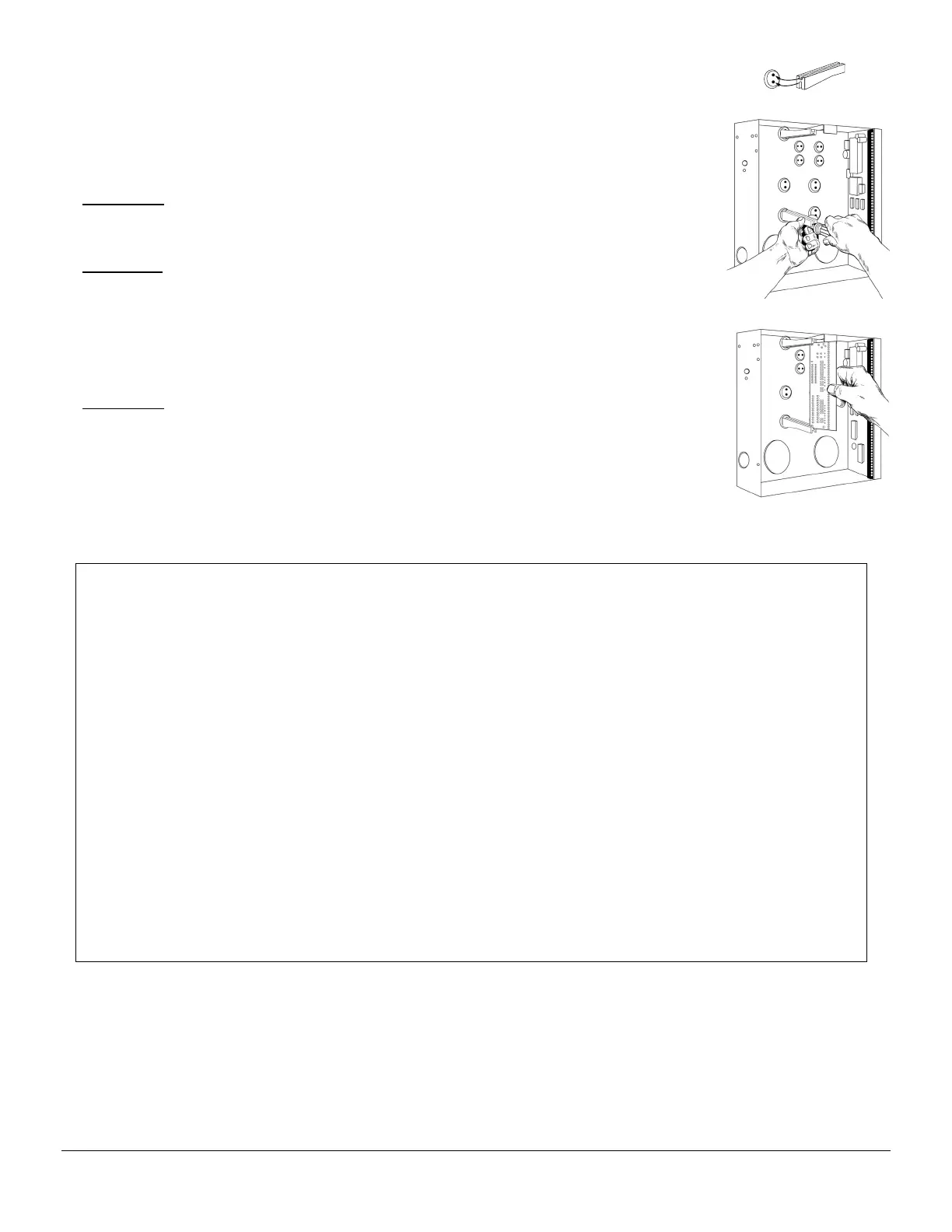
Diagram 1
: The black plastic PCB guides are grooved on one edge where the PC board
will be seated. The end with the half-moon protrusion fits into the larger hole. The
smaller hole is for the screw.
Diagram 2
: Place the first black plastic PCB guide in the top insertion point, grooved edge
downward. The half-moon protrusion will be in the large hole. It does not require force.
Insert one of the provided screw into the smaller hole (from inside the can) to secure it in
place. A screwdriver should reach through the notch that runs the length of the guide to
tighten the screw. The second PBC guide should be positioned opposite the first (grooved
edge up) and placed in the lower insertion point, using the same procedures described
above. Once mounted, screw it in securely.
Diagram 3
: The PC Board should slide freely in the grooves of both guides.
K
IMPORTANT!
1. If separate power supplies are necessary to accommodate additional devices, safety standards
require that each power supply be prominently marked with adequate instructions for
removing all power from the unit.
2. Dispose of used batteries according to the manufacturer’s instructions and/or local government
authorities.
3. Installation personnel should thoroughly read and understand the installation instructions and
the users manuals for the panel and all the accessories to be included with the system before
attempting to install a security system.
WARNING!
Replace only with Panasonic #LC12V4BP or Yuasa #NP4-12 battery. Observe polarity when
installing a new battery. Installing the battery backwards may cause damage to the panel. There is
a risk of explosion if the battery is replaced with an incorrect type.
NOTE
Electrical codes will vary depending upon the country and city where the system is installed. It is
the installer’s responsibility to ensure that the electrical installation is safe and conforms to all
applicable codes, laws, or regulations. Only qualified persons should connect this device to the
mains supply.

 Loading...


