– 26 –
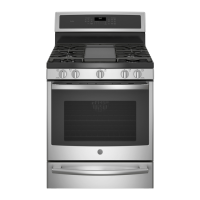
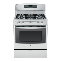
Control Panel Assembly
Touch Panel and Electronic Range Control (ERC)
The glass touch panel and ERC are separate
components, but must be tested together.
TOUCH PANEL TEST
Press each pad on the touch panel, then press the
start pad. If the touch panel is functioning properly,
the following should occur:
• BAKE, WARM, CONVECTION BAKE,
CONVECTION ROAST, SELF CLEAN, COOKING
TIME, KITCHEN TIMER, DELAY START, CLOCK,
OVEN LIGHT, and GAS/CONTROL LOCKOUT
modes – Audible tone plus display showing
mode of operation selected.
• CLEAR/OFF – Audible tone and display shows
time of day.
• PROBE – Audible tone and response if meat
probe is plugged in.
• Numerical Pads – Audible tone. Can only be
used after another function has been selected.
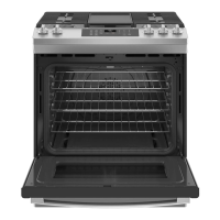
To remove the touch panel and ERC (Profi le and
GE models):
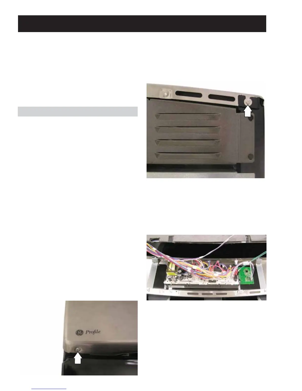
1. Remove the two T-15 Torx screws from the
bottom of the control panel.
WARNING: Components on the control panel are
electrically hot when voltage is connected to the
range.
The control panel assembly consists of a glass
touch panel and an ERC that is attached to a metal
insert panel.
Service Position
(Continued next page)
2. Loosen the two 1/4-in. hex-head screws (1 from
each corner) that attach the top of the control
panel to the range.
3. Place a protective surface over the cooktop.
4. Pull out the bottom of the control panel, then lift
the panel off the range.
5. Place the control panel in the service position as
shown below.
 Loading...