– 34 –
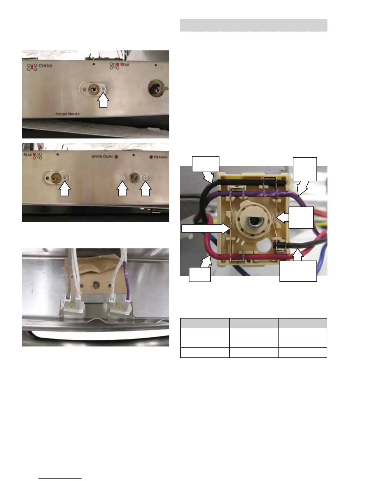
Igniter Switch Assembly
Each surface burner utilizes a switch housing that
is wired to a single harness. Inside each housing
are 2 switches. When the burner valve is advanced
from the OFF position to the LITE position, the
igniter switch closes. The closed igniter switch sends
line voltage to the spark module and activates
all surface burner igniters. At the same time, the
lockout error switch opens and removes previously
applied line voltage from the ERC at location In
WM. When the cooktop is locked out, this removed
voltage allows the ERC to display ERR and sound
a continuous error tone. This informs the user that
they cannot operate the cooktop in the lockout
mode.
Left Rear Switch Housing Shown In Off Position
(cover removed for clarity)
Valve Position Igniter Switch Lockout Switch
OFF Open Closed
LITE Closed Open
On Open Open
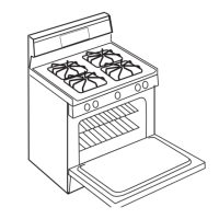
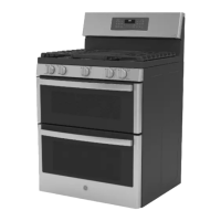
5. Remove the 2 Phillips-head screws and two T-15
Torx screws holding the control panel to the
burner valves.
6. Disconnect the 4 wires from the manifold cover.
(Continued next page)
Igniter Switch
Lockout
Error
Switch
Voltage
to Spark
Module
Voltage to
Motor Lockout
Valve
Line
Voltage
Voltage
from AUX
 Loading...