– 47 –
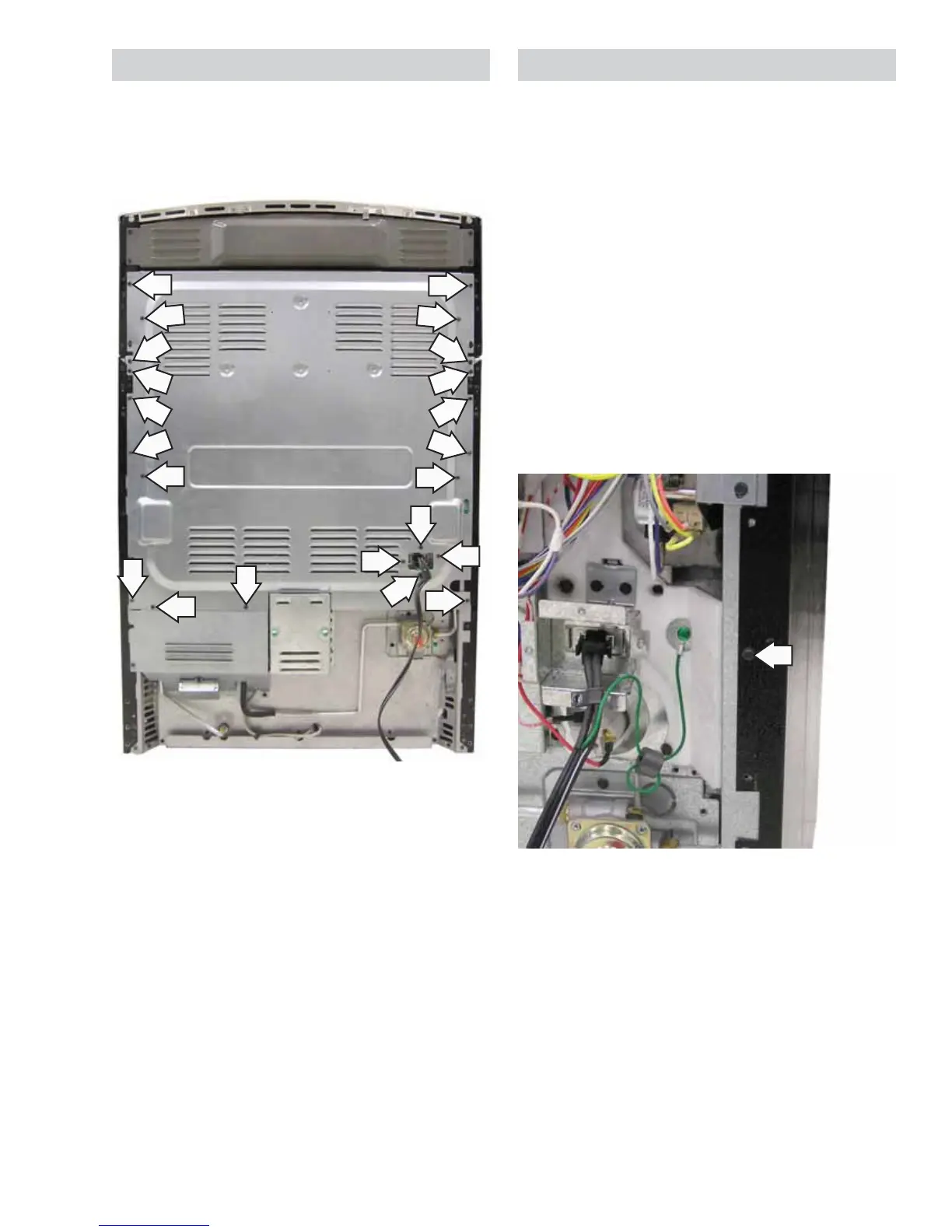
Rear Cover
To access the rear cover, it is necessary to remove
the range from its installation. The rear cover is
attached using twenty-four 1/4-in. hex-head screws
(2 not shown).
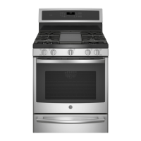
Side Panel
To access the side panel, it is necessary to remove
the range from its installation. The side panel must
be removed to access the upper and lower oven
TCOs, gas lockout valve, latch assembly, and upper
oven lockout relay.
To remove the side panel:
1. On Café models, remove the control panel. (See
Touch Panel and Electronic Range Control (ERC).)
2. On Profi le and GE models, remove the manifold
panel. (See Manifold Panel.)
3. Remove the rear cover. (See Rear Cover.)
4. Remove the remaining 1/4-inch hex-head
screws holding the rear of the side panel to the
frame.
(Continued next page)
 Loading...