– 67 –
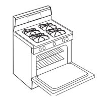
8. Use a 9/16-in. wrench to disconnect the gas
tube from the gas coupler.
9. Remove the two 5/16-in. hex-head nuts holding
the gas valve to the bracket.
9/16-in. Nut
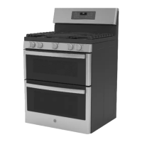
Oven Light Assemblies
The light assemblies are located on the rear of
the oven liner. The oven door switch monitors
the position of the oven door and provides this
information to the control board. The control board
operates the light relay located on the control
board. The lights come on when the OVEN LIGHT
selection on the glass touch panel is activated, the
door is opened, or when the oven is in a cooking
cycle. The oven lights do not come on during the
self-clean cycle or if the sabbath feature is set.
Each light assembly consists of a removable
light cover, a wire harness, and a light lens with a
halogen bulb and socket.
On Café models, the oven light resistance can be
checked by removing the rear cover. (See Rear
Cover.) Each oven light bulb has an approximate
resistance value of 26.8 .
On Profi le and GE models, the resistance of the
light bulb circuit can be checked on the ERC. Place
the control panel in the service position. (See Touch
Panel and Electronic Range Control (ERC)
.)
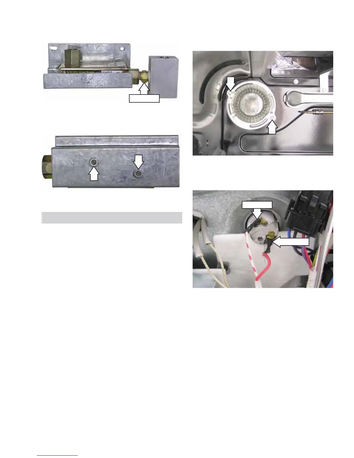
Pull the light assembly away from the oven liner to
access and disconnect the 2 wires.
Disconnect
Disconnect
To access each oven light assembly, open the oven
door and remove the two 1/4-in. hex-head screws
that attach the light assembly to the oven liner.
 Loading...