Installation
(cont’d)
DANGER
HAZARDOUS VOLTAGE
(Can Cause Severe Injury or Death)
Turn OFF all power before installation, adjustment, or removal of transfer switch or any of its components.
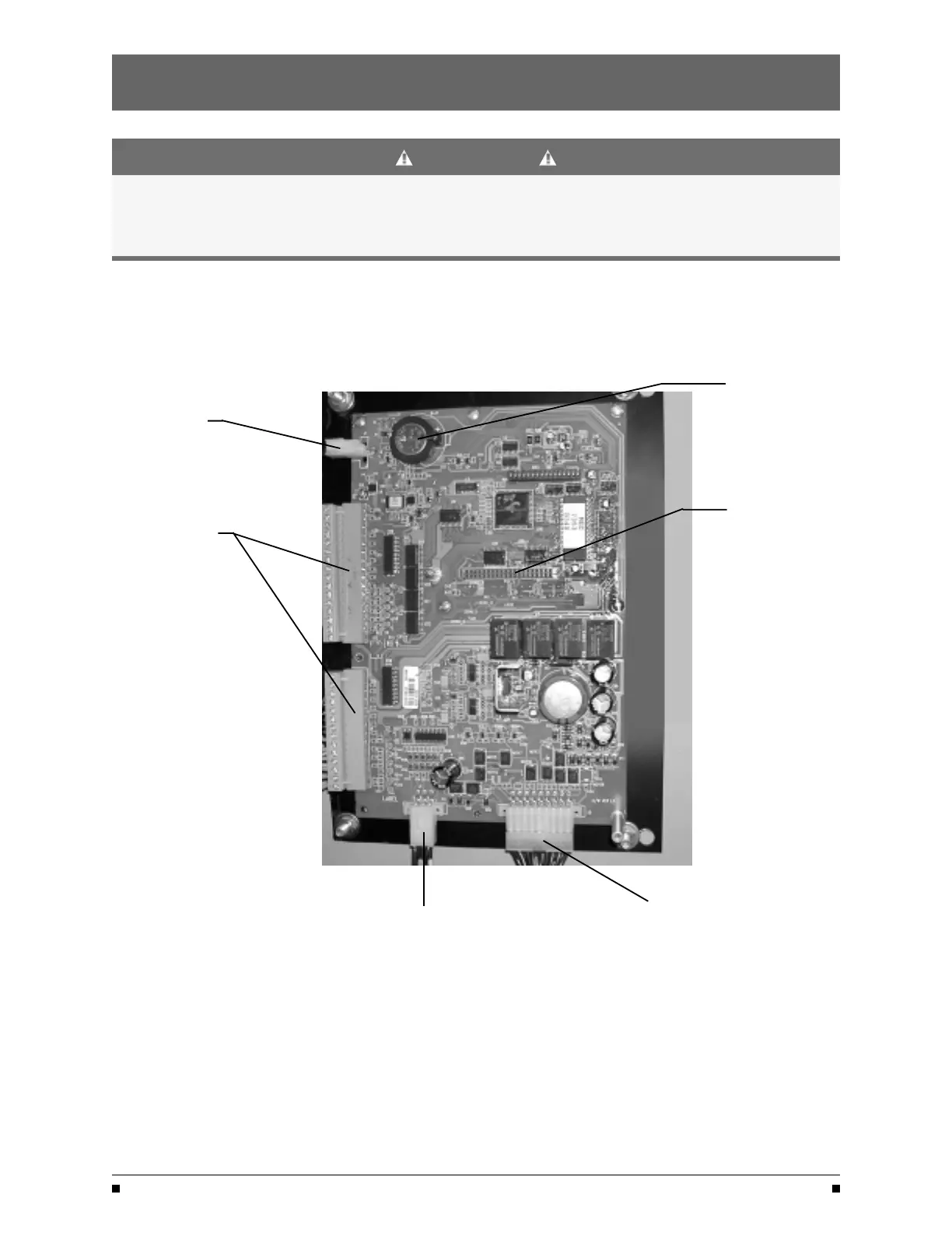
Control Connections
Figure 5
Clock Program
Backup Battery
Remove protective
Connections
Engine Start
strip to enable clock
functions
Network Connector
Input/Output
Connectors
to I/O Modules
To R/T Box
To Power
Panel
A complete information package is furnished with
each transfer switch including a complete connection
diagram and schematic which details all necessary
control circuit field connections.
The engine start control wires connect to the
engine start relay terminals located to the left
of the microprocessor
. Figure 5 shows the location
of these terminals.
The terminals are clearly identified by a label on the
microcontroller backplate. In the case of manual trans
-
fer switches, or in other applications not requiring the
microprocessor
, clearly marked terminal blocks are
provided in the upper left corner of the control panel
for the engine start control wires.
GE Zenith Controls
ZTS / ZTSD Operation and Maintenance Manual (71R-3000)
5
 Loading...