4 ADV20 QS, V1.02
Italiano English
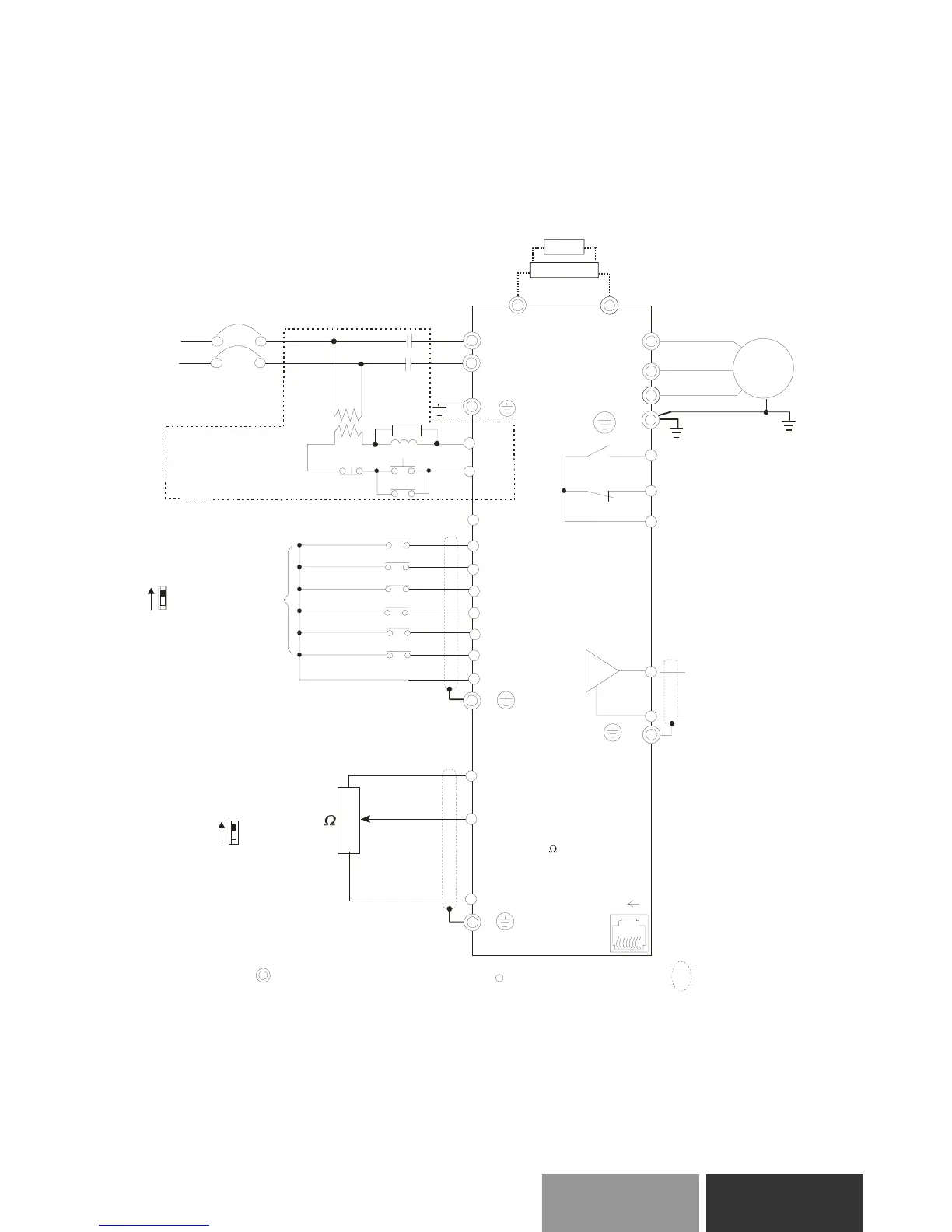
Basic Wiring Diagram
Users must connect wiring according to the following circuit diagram shown below.
Figure 1 for models of ADV20-…-…-1M/2M Series
AVI/ACI
AC M
+
+10V
5K
3
2
1
Power supply
+10V 3mA
Master Frequency
0 to 10V 47k
Analog Signal Common
E
Main circuit (power) terminals
Control circuit terminals Shielded leads & Cable
E
R(L1)
S(L2)
Fu se/NF B(
None Fuse Breaker)
SA
OFF
ON
MC
MC
RB
RC
Recommended Circuit
when power supply
is turned OFF by a
fault output
R(L1)
S(L2)
E
Analog Multi-function Output
Termi nal
factory setting: Analog freq.
/ current meter
0~10VDC/2mA
U(T1)
V(T2)
W(T3)
IM
3~
AFM
AC M
RA
RB
RC
Motor
Analog Signal common
E
E
MI 1
MI 2
MI 3
MI 4
MI 6
MI 5
DCM
+24V
FWD/Stop
REV/Stop
Multi-step 1
Multi-step 2
Multi-step 3
Multi-step 4
Digital Signal Common
Factory
setting
AVI
ACI
Factory setting:
AVI Mode
-
RS-485
Serial interface
1: Reserved
2: EV
5: SG+
6: Reserved
7: Reserved
8: Reserved
3: GND
4: SG-
8
1
Sw1
NPN
PNP
Factory setting:
NPN Mode
Please refer to Figure 3
for wiring of NPN
mode and PNP
mode.
BUE
braking unit
(optional)
BR
braking resistor
(optional)
Multi-function contact output
240Vac 2.5A Max.
120Vac 5A Max.
28Vdc 5A Max.
Factory setting is
“Fault indication”
Factory setting: output frequency
/ 4-20mA
Sw2
 Loading...