ADV20 QS, V1.02 21
Italiano English
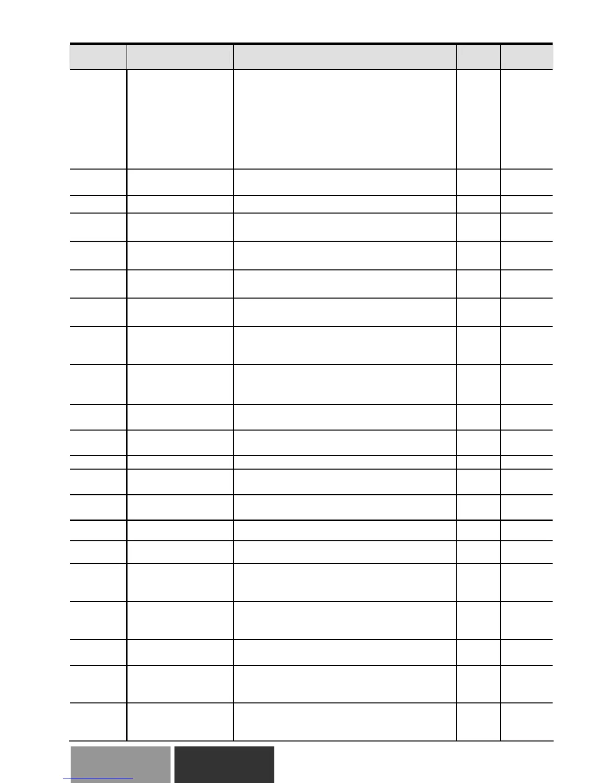
Parameter Explanation Settings
Factory
Setting
NOTE
10.01
Input Terminal for
PID Feedback
0: Positive PID feedback from external
terminal AVI (0 ~ +10VDC)
1: Negative PID feedback from external
terminal AVI (0 ~ +10VDC)
2: Positive PID feedback from external
terminal ACI (4 ~ 20mA)
3: Negative PID feedback from external
terminal ACI (4 ~ 20mA)
0
a10.02
Proportional Gain
(P)
0.0 to 10.0 1.0
a10.03 Integral Time (I)
0.00 to 100.0 sec (0.00=disable)
1.00
a10.04
Derivative Control
(D)
0.00 to 1.00 sec
0.00
10.05
Upper Bound for
Integral Control
0 to 100% 100
10.06
Primary Delay Filter
Time
0.0 to 2.5 sec 0.0
10.07
PID Output Freq
Limit
0 to 110% 100
10.08
PID Feedback
Signal Detection
Time
0.0 to 3600 sec (0.0 disable) 60.0
10.09
Treatment of the
Erroneous PID
Feedback Signals
0: Warn and RAMP to stop
1: Warn and COAST to stop
2: Warn and keep operation
0
10.10
Gain Over the PID
Detection Value
0.0 to 10.0 1.0
a10.11
Source of PID Set
point
0.00 to 600.0Hz
0.00
10.12 PID Feedback Level 1.0 to 50.0% 10.0
10.13
Detection Time of
PID Feedback
0.1 to 300.0 sec 5.0
10.14
Sleep/Wake Up
Detection Time
0.0 to 6550 sec 0.0
10.15 Sleep Frequency 0.00 to 600.0 Hz 0.00
10.16 Wakeup Frequency 0.00 to 600.0 Hz 0.00
10.17
Minimum PID
Output Frequency
Selection
0: By PID control
1: By minimum output frequency (Pr.01.05)
0
10.18
PID Control
Detection Signal
Reference
1.0 to 99.9 99.9
10.19
PID Calculation
Mode Selection
0: Series mode
1: Parallel mode
0
10.20
Treatment of the
Erroneous PID
Feedback Level
0: Keep operating 1: Coast to stop 2: Ramp
to stop 3: Ramp to stop and restart after time
set in Pr.10.21
0
10.21
Restart Delay Time
after Erroneous PID
Deviation Level
1 to 9999 sec 60
 Loading...