1380415F_MSW_GFX4-IR_05-2019_ENG
- Signals coming from custom thermocouples
An alternate linearization is available only for sensors consisting of custom thermocouples, created by dening engineering
values at three measurement scale points settable with the following parameters:
295
S.35
R/W
Engineering value attributed to input
signal corresponding to 50°C.
mV at 50° C
(- 1.999 ... 9.999)
294
S.34
R/W
Engineering value attributed to maxi-
mum value of the input scale.
mV full scale
((S.33+1) ... 99.99)
293
S.33
R/W
Engineering value attributed to minimum
value of the input scale.
mV start of scale
(- 19.99 ... 99.99)
86
S.00
R/W
Engineering value attributed to Point 0
(minimum value of input scale)
(- 1999 ... 9999)
118
S.32
R/W
Engineering value attributed to
Point 32
(maximum value of input scale)
(- 1999 ... 9999)
87
S.01
R/W
Engineering value attributed to
Point 1
(- 1999 ... 9999)
. . . . .
intermediate values
For correct signaling of error state (Lo, Hi), the value
set in S.00 must coincide with limit Lo.S and the
value set in S.32 with limit Hi.S.
The engineering values calculated in this way by the user can be set by means of the following parameters.
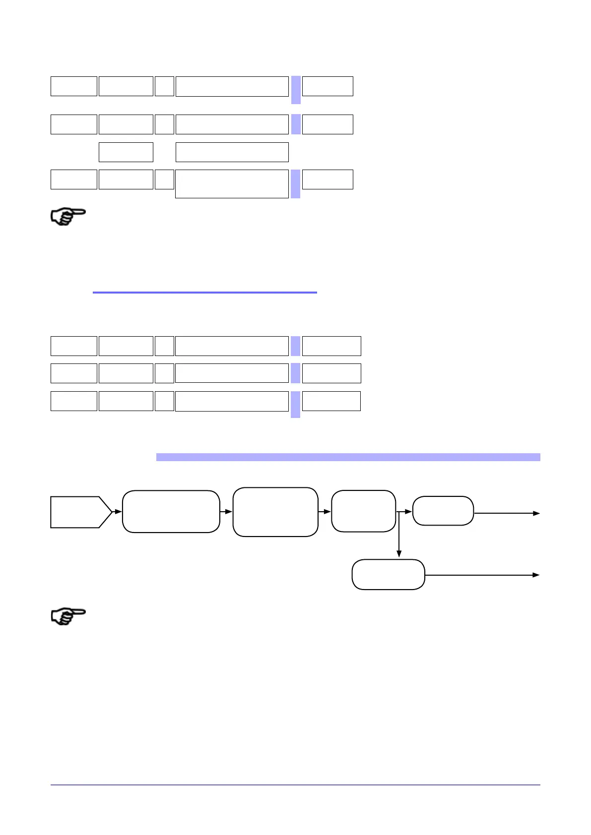
FUNCTIONAL DIAGRAM
N.B. The decimal point does not change the
contents of the PV, but only permits its correct
interpretation.
Ex.: if dP.S = 1 and PV = 300, the engineering value
in °C is 30.0.
Input
signal
Probe type (tYP).
Linearization of signal
(S00...S35)
Scale limits and
decimal point
(Hi.S, Lo.S, dP.S ).
Offset (OfS).)
Low pass
lter
(FIt)
Process
variable (PV)
Select PV
for zone
See control
Digital lter
(FId)
Variable DPV

 Loading...


