4380415F_MSW_GFX4-IR_05-2019_ENG
SETTINGS
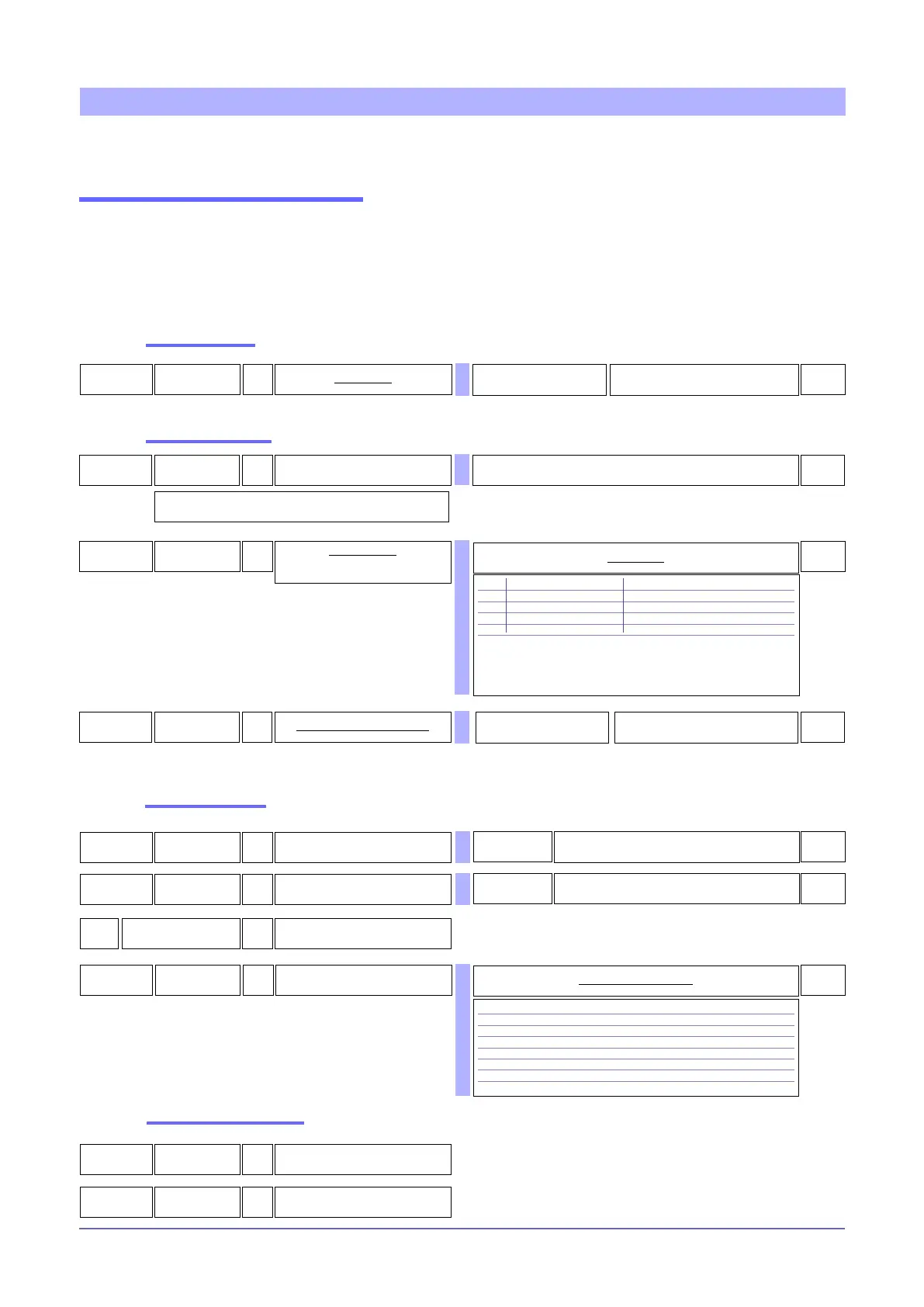
The controller has the following setpoint controls.
SETTING THE SETPOINT
Local setpoint
138
16 - 472
sp
R/W
Local setpoint
0
Remote setpoint
Read active setpoint
1
137 - 481
spa
R Active setpoint
25
20 - 28 - 142
Lo.L
R/W
Lower settable limit
SP, SP.1, SP.2, SP remote
Lo.S ... Hi.S
0
26
21 - 29 - 143
xI.L
R/W
Upper settable limit
SP, SP.1, SP.2, SP remote
Lo.L ... Hi.S
1000
181
tp.2
R/W
Auxiliary analog input function
0
See: AUXILIARY ANALOG INPUT (LIN/TC)
The remote setpoint can be set by means of the auxiliary analog
input by enabling the function with parameter tP.2
Shared settings
The active (control) setpoint (SPA) can be set by means of the local setpoint (_SP) or the remote setpoint (SP.rS). A
remote setpoint can assume the value of an auxiliary input or one set via serial line (SP.r).
The remote setpoint can be dened in absolute value or relative to the local setpoint; in the latter case, the control
setpoint will be given by the algebraic sum of the set local and the remote setpoint.
10
bit
LOCAL/REMOTE
OFF = Enable local setpoint
ON = Enable remote setpoint
R/W
18
136 - 249
SP.r
R/W
Remote setpoint
(SET gradient for manual power
correction)
0
Type of remote set Absolute/Relative
0 Digital (from serial line) Absolute
1 Digital (from serial line) Relative to local set (_SP o SP1 o SP2)
2 Auxiliary input Absolute
3 Auxiliary input Relative to set (_SP o SP1 o SP2)
+4 set gradient in digit/sec.
+8 manual power correction based on line voltage
+16 disables saving of local setpoint _SP
+32 disables saving of local manual power (at switch-off, returns to last value
saved)
Setpoint table
4
R
Deviation (SPA - PV)
305
R/W
Instrument state (STATUS_W)
bit
0 -
1 Select SP1/SP2
2 Start/Stop Selftuning
3 Select ON/OFF
4 Select AUTO/MAN
5 Start/Stop Autotuning
6 Select LOC/REM
Table of instrument settings
Lo.L....HI.L
250 SERIAL_SP
R/W
Remote Setpoint from serial line
0
Lo.L....HI.L

 Loading...


