2180415F_MSW_GFX4-IR_05-2019_ENG
AUXILIARY ANALOG INPUT (LIN/TC)
The GFX4-IR has 4 inputs defined as auxiliary (IN5 for zone 1, IN6 for zone 2, IN7 for zone 3, IN8 for zone 4) to which
TC or linear temperature sensors can be connected.
The presence of these inputs is optional and, for model GFX4-IR-x-x-4-x-x is defined by the order code.
The input value, saved in variable In.2, can be read and used to activate the alarm signals assigned to it.
When an auxiliary input is present, you have to dene the following parameters:
- sensor type (AI.2);
- its function (tP.2);
- decimal point position (dP.2);
- scale limits (HS.2 – LS.2);
- offset correction value (oFS.2).
If the sensor is a thermocouple, the minimum and maximum limits can be dened in the specic scale of the sensor
used. The range of values settable for alarm setpoints depends on these limits.
There is also a digital lter (Flt.2) that can be used to reduce noise on the input signal.
194
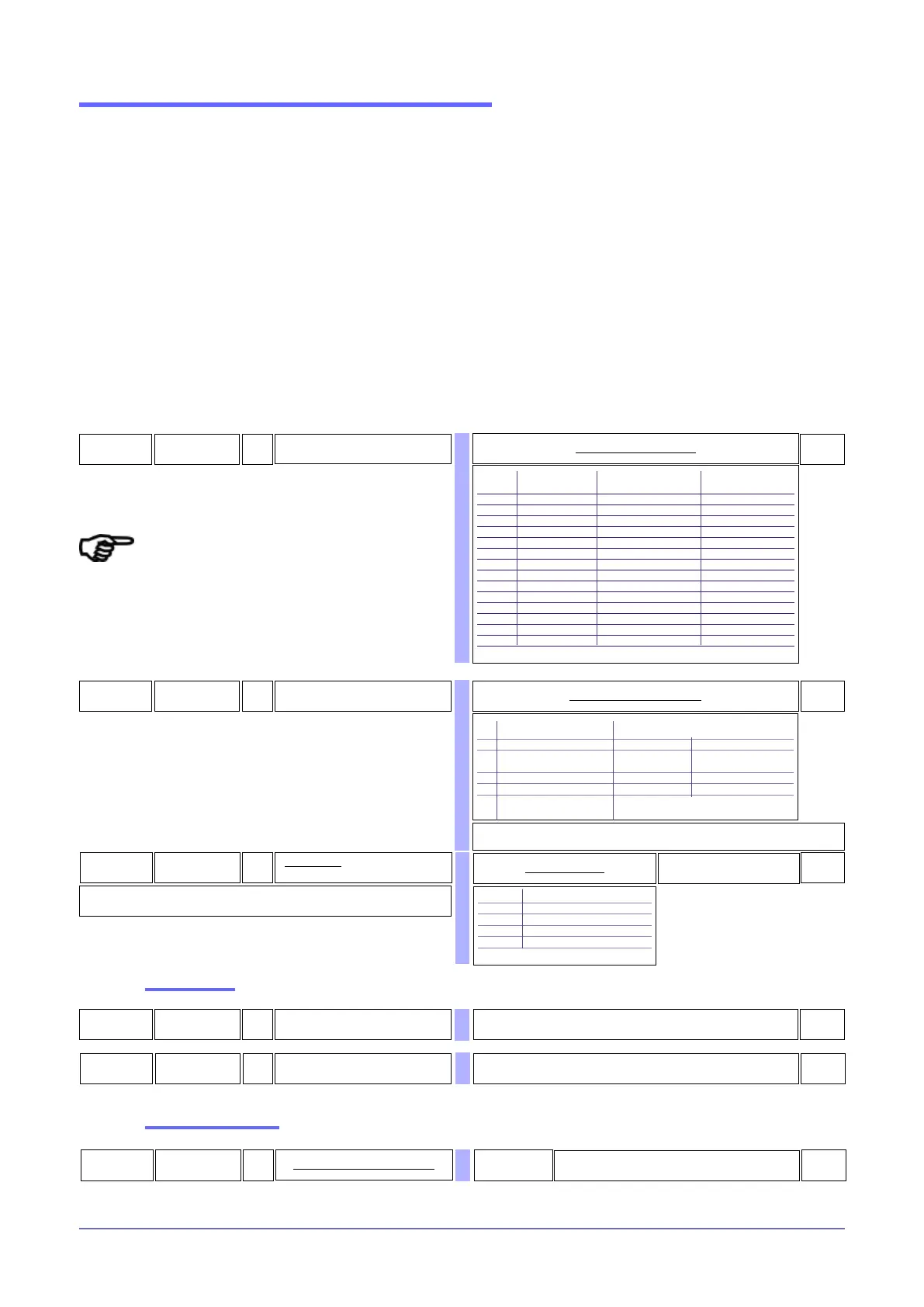
AI.2
R/W
Select type of auxiliary sensor input
0
Type of probe Without dec. point With dec. point
or sensor
0 TC J °C 0/1000 0.0/999.9
1 TC J °F 32/1832 32.0/999.9
2 TC K °C 0/1300 0.0/999.9
3 TC K °F 32/2372 32.0/999.9
4 TC R °C 0/1750 0.0/999.9
5 TC R °F 32/3182 32.0/999.9
6 TC S °C 0/1750 0.0/999.9
7 TC S ° F 32/3182 32.0/999.9
8 TC T °C -200/400 -199.9/400.0
9 TC T °F -328/752 -199.9/752.0
34 0...60 mV -1999/9999 -199.9/999.9
35 0...60 mV Custom linearization Custom linearization
36 12...60 mV -1999/9999 -199.9/999.9
37 12...60 mV Custom linearization Custom linearization
99 Input off
Auxiliary inputs sensors table
181
tp.2
R/W
Definition of auxiliary analog input
function
Auxiliary LIMITS FOR SETTING the LS.2 and HS.2
input function min max
0 None -1999 9999
1 Remote setpoint Absolute Lo.S, Absolute Hi.S,
deviation -999 deviation +999
2 Manual analog remote -100.0% +100.0%
3 Reset analog power -100.0% +100.0%
10 Remote manual analog
from main input
0
Table of auxiliary input functions
(*)
(*)
(**)
603
XS.2
R/W
Maximum limit of auxiliary input scale
Min...max input scale selected in AI.2 and tP.2
1000
404
LS.2
R/W
Minimum limit of auxiliary input scale
Min...max input scale selected in AI.2 and tP.2
0
605
oFS.2
R/W
Offset for auxiliary input correction
-999 ...999
Scale points
0
Scale limits
Setting the offset
(*) see: Settings – Control Setpoint
(**) see: Controls –PID Parameters
Calibrate the UCA inputs by means of the GFX-
OP terminal.
The procedure is described in the GFX-OP
manual.
677
dP.2
R/W
Decimal point position for the auxiliary
input scale
Format
0 xxxx
1 xxx.x
2 xx.xx (*)
3 x.xxx (*)
(*) not available for TC probes
Decimal point table
0
Species the number of decimal gures used to represent the input signal value: for
example, 875.4 (°C) with dP.S: = 1
(*)

 Loading...


