980415F_MSW_GFX4-IR_05-2019_ENG
46
(od
R
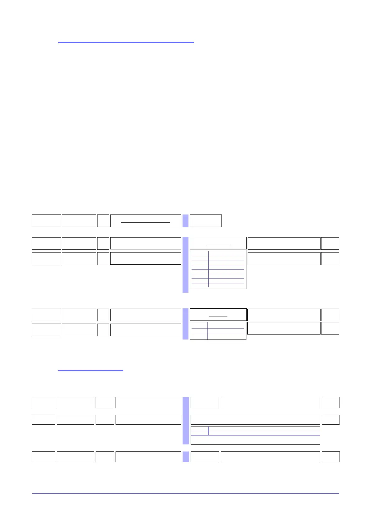
Instrument identification code
1 ... 99
45
baV
R/W
Select Baudrate - Serial 1
4
0 1200 bit/s
1 2400 bit/s
2 4800 bit/s
3 9600 bit/s
4 19200 bit/s
5 38400 bit/s
6 57600 bit/s
7 115200 bit/s
Baudrate table
626
bav.2
R/W
Select Baudrate - Serial 2
4
Installation of the “MODBUS” serial network
A network typically has a Master that “manages” communication by means of “commands” and Slaves that interpret
these commands.
GFX4-IRs are considered Slaves to the network master, which is usually a supervision terminal or a PLC.
They are positively identied by means of a node address (ID) set on the rotary switches (tens + ones).
GFX4-IRs have a ModBus serial (Serial 1) and optional Fieldbus (Serial 2) serial (see order code) with one of the
following protocols: ModBus, Probus, CANopen, DeviceNet, Ethernet.
The following procedures are indispensable for the Modbus protocol.
For the remaining protocols, see the specic Geex Probus, Geex CANopen, Geex DeviceNet and Geex Ethernet manuals.
GFX4-IR modules have the following default settings:
- node address = 0 (0 + 0)
- speed Serial 1 = 19200 bit/s
- parity Serial 1 = none
- speed Serial 2 = 19200 bit/s
- parity Serial 2 = none
You can install a maximum of 99 GFX4-IR modules in a serial network, with node address selectable from “01” to “99” in stan-
dard mode, or create a mixed GFX4-IR/ GFX4 / Geex network in Geex compatible mode in which each GFX4-IR or GFX4
identies 4 zones with sequential node address starting from the code set on the rotary switches.
In short, the valid rotary switch settings (tens + ones) are:
- (0 +0) = Autobaud Serial 1
- (B +0) = Autobaud Serial 2
- (A + 0) = Autonode Serial 1 for Geex slaves connected to GFX4-IR.
47
par
R/W
Select parity - Serial 1
0
0 No parity
1 Odd
2 Even
Parity table
627
par.2
R/W
Select parity - Serial 2
0
Communication error
If Modbus communication between GFX4-IR and Master node goes into timeout (settable in C.E.t parameter), you can
force an output power value (C.E.P parameter of each zone) and transmit the alarm state to a relay output (rL.x parameters).
890
[.E.T
R/W Timeout for communication error 0 ... 121 sec. Value 0 disables the function
0
891
[.E.
m
R/W Mode for communication error Mode table for communication error
0
0 Delivered power is not changed
1 La potenza erogata viene forzata al valore C.E.P
+16 only for C.E.M -1 in MANUAL_POWER at the restart of the
communication (only if in manual mode)
892
[.E.P
R/W
Output power when
communication error is active
-100.0...100.0%
0,0

 Loading...


