EasyManua.ls Logo

gefran QE1008-W SET User Manual

gefran QE1008-W SET
38 pages
To Next Page IconTo Next Page
To Previous Page IconTo Previous Page
Page #34 background image
34
Subject to technical modications
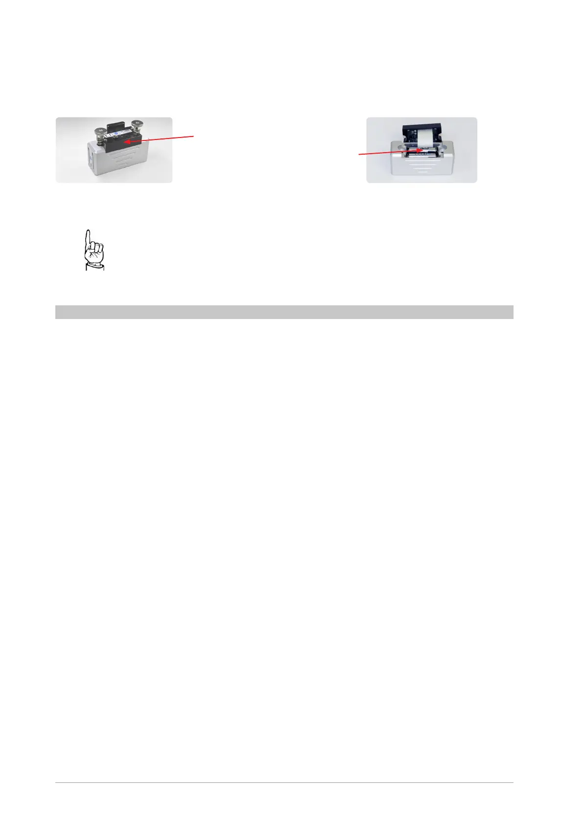
Replacing the batteries
1. Switch o󰀨 the sensor
2. Carefully remove the plastic cover.
3. Replace the rechargeable batteries
4. Close the cover using the four M2.5 x 20mm pan-head screws
Normal AAA batteries can be used in an emergency. These may only
be used temporarily and must be replaced as soon as possible with
rechargeable batteries!
Normal AAA batteries must NOT be charged!
12.2. Servicing
The QE1008-W sensors should be calibrated every 12 months. In order to calibrate them, the
sensors must be sent to Sensormate AG.
Trained and qualied sta󰀨 of Sensormate AG can recalibrate the QE1008-W sensors.
AAA
rechargeable batteries
NiMH
Plastic cover

Questions and Answers:

gefran QE1008-W SET Specifications

General IconGeneral
Brandgefran
ModelQE1008-W SET
CategoryMeasuring Instruments
LanguageEnglish

Summary

1. PREFACE

2. WEEE INFORMATION

3. INTENDED USE

4. BASIC SAFETY REGULATIONS

4.1. Explanation of symbols

Explains symbols used in the manual for safety.

4.2. Basic safety regulations

General accident prevention and safety legislations.

4.3. Organisational measures

Manual availability and adherence requirements.

5. LIABILITY AND WARRANTY

5.1. Area of application

Defines the intended use and scope of the sensors.

5.2. Exclusion of liability and warranty

Conditions voiding liability and warranty.

6. PRODUCT DESCRIPTION

6.1. Introduction

Overview of QE1008-W sensors for force and strain measurement.

6.2. Scope of delivery

Lists items included in the QE1008-W sensor kit.

6.3. Technology

Explains magnetic press-on technology and applications.

7. TECHNICAL DATA

7.1. QE1008-W (Sensor)

Technical specifications for the QE1008-W sensor unit.

7.2. BLUETOOTH TRANSCEIVER-MODULE

Technical dimensions for the QE Booster (Bluetooth receiver).

7.3. USB TRANSCEIVER-MODULE

Technical dimensions for the USB transceiver module.

8. TERMINOLOGY

Technical Terms and Definitions

Defines technical terms like DMS, FS, Accuracy, Linearity, Hysteresis.

9. MOUNTING AND INSTALLATION

9.1. Mounting for bending compensated tie bar strain measurement

Instructions for mounting sensors for specific measurement types.

9.1.1. Preparation

Steps to prepare for sensor mounting, including position and surface.

9.1.2. Positioning the sensor

Detailed steps for correctly positioning the sensor on the tie bar.

10. OPERATION AND CONTROL

10.1. Sensor QE1008-W

Details on sensor components, LED status, and button functions.

10.2. QE Booster

Operation and control of the QE Booster device.

10.3. Sensormate App

Installation and operation of the Sensormate mobile application.

10.4. Wireless receiver QE1008-W-G

Details on the wireless receiver's LEDs and button functions.

10.4.1. Activating the system

Steps to activate the sensor system and connect to the PC.

10.4.2. Assigning a QE1008-W sensor

Procedure for assigning a QE1008-W sensor to a wireless receiver slot.

10.4.3. New assignment of all QE1008-W sensors

Process for deleting and reassigning all sensors to the wireless receiver.

10.5. Measuring the tie bar strain distribution

Guide on how to measure strain distribution on tie bars.

10.6. Measuring the tie bar bending (tie bar crack detection)

Method for measuring tie bar bending and detecting cracks.

11. TROUBLESHOOTING

12. MAINTENANCE OF QE1008-W SENSORS

12.1. Inspection

Procedures for inspecting the sensor's foil and magnets.

12.1.1. Foil

Specific inspection instructions for the sensor foil.

12.1.2. Magnet

Specific inspection instructions for the sensor magnets.

12.1.3. Rechargeable Batteries

Instructions for charging and status display of rechargeable batteries.

12.2. Servicing

Information on sensor calibration and sending for service.

13. ACCESSORIES AND SPARE PARTS

15. NOTES

Related product manuals