www.gemu-group.com 23 / 76 GEMÜ 1436 cPos
NOTICE
▶ The adapter lug 4 must engage in the actuator shaft
groove.
4. Mount the mounting bracket 6 on the actuator 3 using the
screws, washers and spring washers provided.
5. The 5-pin M12 rotary travel sensor connector must be con-
nected to the 5-pin M12 socket on the base of the product.
6. Connect the pneumatic supply to the positioner and con-
nect to the quarter turn actuator 3.
NOTICE
Note for the rotary travel sensor
▶ The slotted holes should be positioned in the centre on
the screws. If the travel is not correctly set (determined
by checking the attachment), loosen the two screws
slightly and twist the travel sensor. Set the travel up cor-
rectly and tighten the screws again.
11.10 Checking the mechanical mounting
1. Connect the product to the power (see “Electrical connec-
tion“, page25) and air supply (see “Pneumatic connec-
tion“, page23) (see electrical connection and pneumatic
connection).
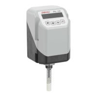
2. The following message is displayed:
3. By pressing the and keys, the mounted actuator
can be moved to the OPEN and CLOSED position.
4. Important: The displayed valve position must be between
2% and 98%. If the display leaves this area, check the
mechanical mounting again and, if necessary, readjust the
orientation of the rotary travel sensor. In the case of linear
travel sensors, check the mounting parts used for compat-
ibility.
11.11 Mounting the mounting bracket
NOTICE
● Ensure adequate stability of the base used for attach-
ment.
● The product must be protected against mechanical
stress by the operator.
● Do not use the product as a foothold.
1. Push the product connection adapter through the hole in
the mounting bracket and fix it with the enclosed nut.
2. Use the bolt holes and appropriate fixings to attach the
mounting bracket securely.
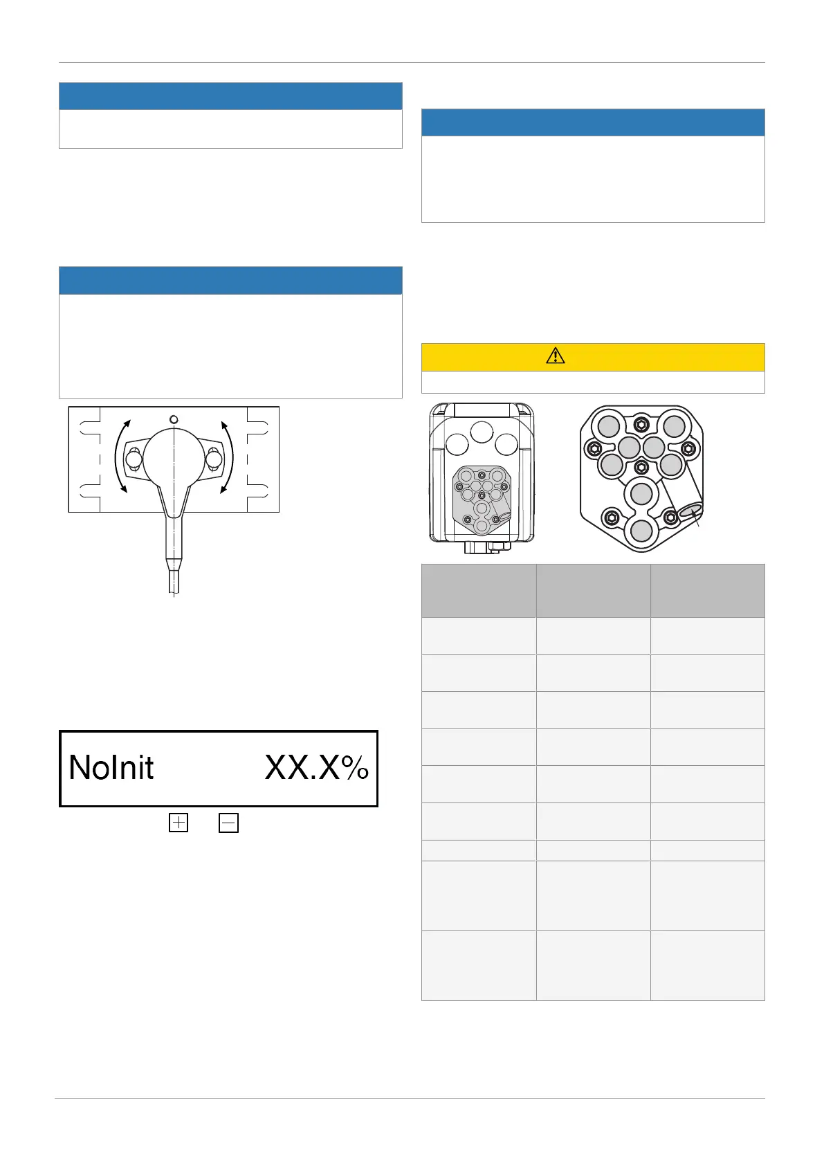
12 Pneumatic connection
CAUTION
▶ Observe the maximum control pressure of the actuator.
Connection in ac-
cordance with
DIN ISO 1219-1
Designation Size
1 Air supply connec-
tion
G1/8
3 Venting connection
with silencer
G1/8
V1 Supply air throttle
for connector 2
-
V2 Exhaust air throttle
for connector 2
-
V3 Exhaust air throttle
for connector 4*
-
V4 Supply air throttle
for connector 4*
-
V5 Check valve -
2 Working connec-
tion for process
valve (control func-
tion 1 and 2)
G1/8
4 Working connec-
tion for process
valve (control func-
tion 3)
G1/8
* only double acting type (code 3)
12 Pneumatic connection
 Loading...