www.gemu-group.com 25 / 76 GEMÜ 1436 cPos
12.2.2 Connection diagram for double acting valves
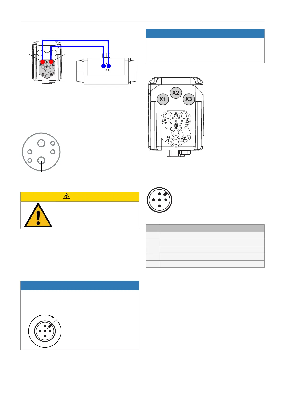
Fit tubing from 2 to connector 2 of the quarter turn actuator
and 4 to connector 4 of the quarter turn actuator.
12.2.3 Note for vertical pneumatic connections
In the case of a vertical connection, please observe the follow-
ing pneumatic connection assignment:
12.3 General information
CAUTION
Exhaust air and cycle duties generate
noise
▶ Hearing damage
● Wear hearing protection
The exhaust air connection is equipped with a silencer as
standard to reduce noise emissions. Other commercially
available silencers with G1/8 male thread can also be fitted.
Alternatively, the recessed G1/8 thread can be used to attach
commercially available pneumatic screw connections in order
to be able to discharge the exhaust air in a targeted manner.
13 Electrical connection
NOTICE
Risk of cable break
▶ Overtightening can result in damage to the internal
cables.
● Turn electrical connections once by max. 360°.
NOTICE
Voltage cutoff
▶ To ensure safe start-up of the positioner following inter-
ruption of the power supply, the power interruption must
be longer than three seconds.
Position of the connectors
13.1 24 V, ordering option Fieldbus, code 000
Position of the connectors
Connection X1
5-pin M12 plug, A-coded
Pin Signal name
1 U
v
, 24 V DC supply voltage
2 Switching output K1, 24 V DC (switches Uv
1)
)
3 GND, (supply voltage, DigIn1+2+W +X; K1+2)
4 Switching output K2, 24 V DC (switches Uv
1)
)
5 Digital input 1 (only for Option code 01)
1) Switching output switches device supply voltage U
v
- drop voltage
13 Electrical connection

 Loading...