2-1
SECTION 2: IGNITION
SECTION CONTENTS
PAGE
SPECIFICATIONS............................................................. 2-1
GENERAL INFORMATION................................................ 2-1
ARMATURES
Armature Testing ...................................................... 2-1
Removing Armatures ................................................ 2-1
Install Armatures........................................................ 2-1
Adjust Armature Air Gap .......................................... 2-2
FLYWHEEL
Remove Flywheel ...................................................... 2-2
Inspect Flywheel Key and Keyways ............................ 2-2
Install Flywheel .......................................................... 2-3
ENGINE WIRING HARNESS ............................................2-3
Testing Ground Wires ................................................ 2-3
Engine Wiring Harness Diagram ................................ 2-4
Diode Failure Diagnosis ............................................ 2-4
SPECIFICATIONS FOR
GTV-990/760 OHVI V-TWIN ENGINE
MODEL SERIES................................................ GTV-990/760
ARMATURE AIR GAP .............................. 0.20 TO 0.30 MM
(0.008" TO 0.012")
FLYWHEEL NUT TORQUE
FT. LBS. ........................................................................ 150
FLYWHEEL NUT TORQUE
NM .............................................................................. 203
See Section 1 For Spark Plug Maintenance And Specifications
GENERAL INFORMATION
Generac GTV-990/760 OHVI V-Twin engines use a magneto
ignition: an ignition armature with a self-contained transistor
module (no moving parts). Two magneto ignition armatures
are used, with a flywheel containing a permanent magnet.
NOTE: The magneto ignition system requires a minimum
of 250 RPM to produce a consistent spark.
ARMATURES
ARMATURE TESTING:
The condition of the ignition armatures can be accurately diag-
nosed using an ignition tester, (Generac P/N 0C5969) as
described in "Troubleshooting" in Section 1.
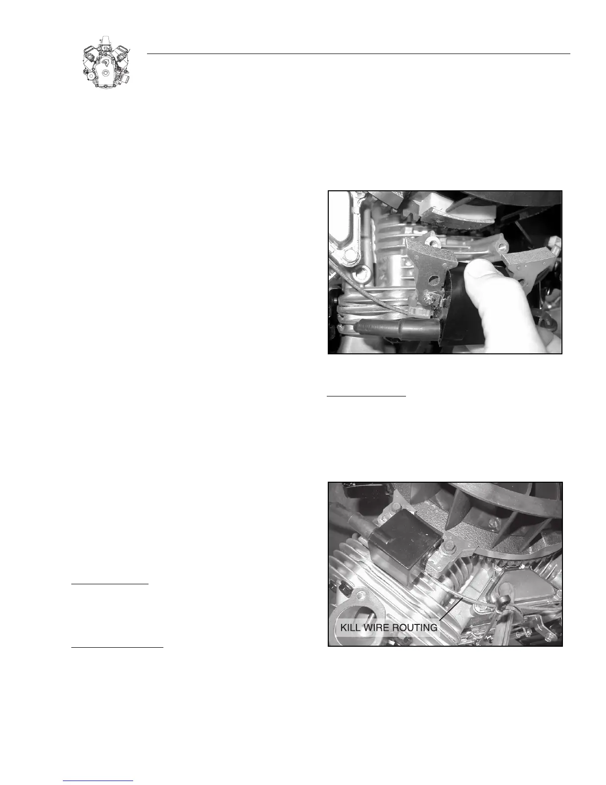
REMOVING ARMATURES:
1. Remove spark plug leads.
2. Remove intake manifold and cover intake ports.
3. Remove rotating screen and blower housing.
4. Remove armature screws and lift off armature(s),
Figure 2-1.
a. Disconnect stop switch wires at armatures.
Note:The flywheel does not need to be removed to ser-
vice ignition except to check the flywheel key.
Figure 2-1. Removing Armature
INST
ALL ARMATURES:
1. Turn flywheel so magnet is away from armature.
2. Install ground wire onto tab terminal on armature.
Note: Make sure wires are routed over armature mount-
ing posts and away from flywheel.
Figure 2-2. Installing Armature
3. Assemble armature to engine, Figure 2-2.
a. Mounting holes in armature are slotted. Push armature
away from flywheel as far as possible and tighten one screw
to hold armature in place.

 Loading...