SECTION 5: CYLINDER HEAD AND VALVES
5-5
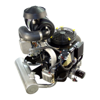
INSTALL CYLINDER HEAD
1.Install cylinder head with new gasket.
2. Torque head bolts in sequence shown to 29.9 Nm (22 ft.
lbs.) (Figure 5-16).
3. Insert push rods into recess in tappets.
Figure 5-16.
ADJUST VALVE CLEARANCE
1.Set No. 1 cylinder at TDC, compression stroke.
a. Adjust rocker arms and check clearance (Figure 5-17).
Figure 5-17. Adjust Valve Clearances
Valve Clearance (cold) IN and EX 0.0762 mm (.003“).
b. Torque jam nut and ball stud to 19 Nm (14 ft. lbs.).
2. Repeat for No. 2 cylinder.
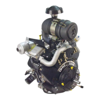
3.Install valve covers with new gaskets, Figure 5-18.
a. Torque nuts to 6.8 Nm (5 ft. lbs.).
Figure 5-18. Install Valve Covers
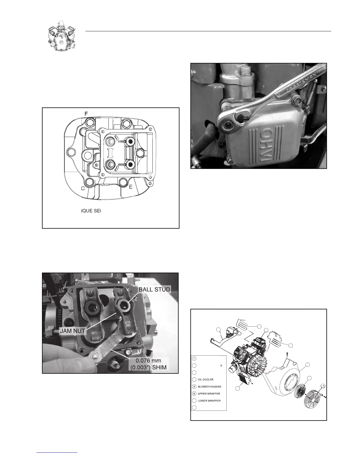
REASSEMBLE
1. Install cylinder wrappers.
a. Torque M5 screws to 2.8 Nm (25 in. lbs).
b. Torque M6 screws to 4.5 Nm (40 in. lbs).
2. Install spark plugs.
a. Torque to 20 Nm (180 in. lbs.).
3. Install exhaust manifold.
a. Torque screws to 19 Nm (14 ft. lbs.).
4. Install blower housing.
a. Torque screws to 4.5 Nm (40 in. lbs).
5. Install intake manifold with new gaskets.
a. Torque screws to 19 Nm (14 ft. lbs.).
b. Assemble governor link to carburetor.
Figure 5-19. General Assembly

 Loading...