10-1
SECTION 10: CYLINDER & CRANKCASE COVER
SECTION CONTENTS
PAGE
CHECK CRANKCASE.................................................... 10-1
Resizing .................................................................. 10-1
Cylinder Finish ........................................................ 10-1
Cleaning.................................................................. 10-2
BEARINGS.................................................................... 10-2
Check Mag Bearing ................................................ 10-2
Remove Mag Bearing .............................................. 10-2
Install Mag Bearing .................................................. 10-3
Check PTO Bearing .................................................. 10-3
Remove/Install PTO Bearing...................................... 10-3
Install PTO Oil Seal .................................................. 10-4
Check Camshaft Bearings ........................................ 10-4
Oil Seals .................................................................. 10-4
CHECK CRANKCASE
Check crankcase for cracks, stripped threads or broken fins.
Check cylinder bores for damage or scoring.
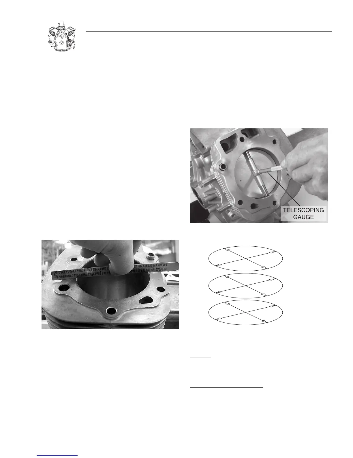
1.Check cylinder head mounting surface for distortion with a
straight edge, Figure 10-1.
If mounting surfaces are distorted more than 0.1 mm (.004"),
the crankcase must be replaced.
Figure 10-1. Checking Cylinder Head Mounting Surface
2.Check cylinder bores for wear using telescoping gauge and
dial caliper.
Standard Bore Size: 90.00-90.025 mm (3.543-3.544”)
a. Measure cylinder bore in 6 points at right angles as shown,
Figures 10-2 and 10-3.
b. If cylinder bore is worn more than 0.075 mm (.003") or
more than 0.035 mm (.0015") out of round, it must be
replaced.
NOTE: If cylinder bores are within specification and show
no signs of scoring or other damage, new piston rings
may be installed providing the cylinder bores are recon-
ditioned using a rigid hone with finishing stones,
to
restore the proper cross hatch angle in the cylinder bores. The
proper cylinder cross hatch ensures proper lubrication and
piston ring break in.
Refer to "Cylinder Finish (Cross Hatch)” below for correct pro-
cedure for installing cross hatch.
Figure 10-2. Check Cylinder Bore
Figure 10-3. Measure at Six Points
RESIZING:
Note: Oversize kits are NOT available. DO NOT bore
cylinder.
CYLINDER FINISH (CROSS HATCH):
Finishing stones are used when reconditioning a cylinder
bore. The finishing stones will produce the correct cross hatch
necessary for proper lubrication. The correct cross hatch angle
is approximately 45 degrees, Figure 10-4.

 Loading...