13-1
SECTION 13: ENGINE ASSEMBLY
SECTION CONTENTS
PAGE
INSTALL CRANKSHAFT ................................................ 13-1
INSTALL PISTON AND CONNECTING ROD .................... 13-1
INSTALL CAMSHAFT .................................................... 13-2
INSTALL OIL PUMP ...................................................... 13-2
INSTALL CRANKCASE COVER ...................................... 13-2
INSTALL ALTERNATOR AND IGNITION COILS ................ 13-3
INSTALL BREATHER ...................................................... 13-3
INSTALL FLYWHEEL ...................................................... 13-3
ADJUST IGNITION COIL AIR GAP .................................. 13-4
INSTALL CYLINDER HEADS .......................................... 13-4
INSTALL ROCKER ARMS .............................................. 13-4
ADJUST VALVE CLEARANCE ........................................ 13-5
GENERAL ASSEMBLY.................................................... 13.5
ADJUST GOVERNOR .................................................... 13-6
INSTALL CRANKSHAFT
Lubricate mag bearing and lips of oil seal with engine oil and
install crankshaft.
Figure 13-1. Installing Crankshaft
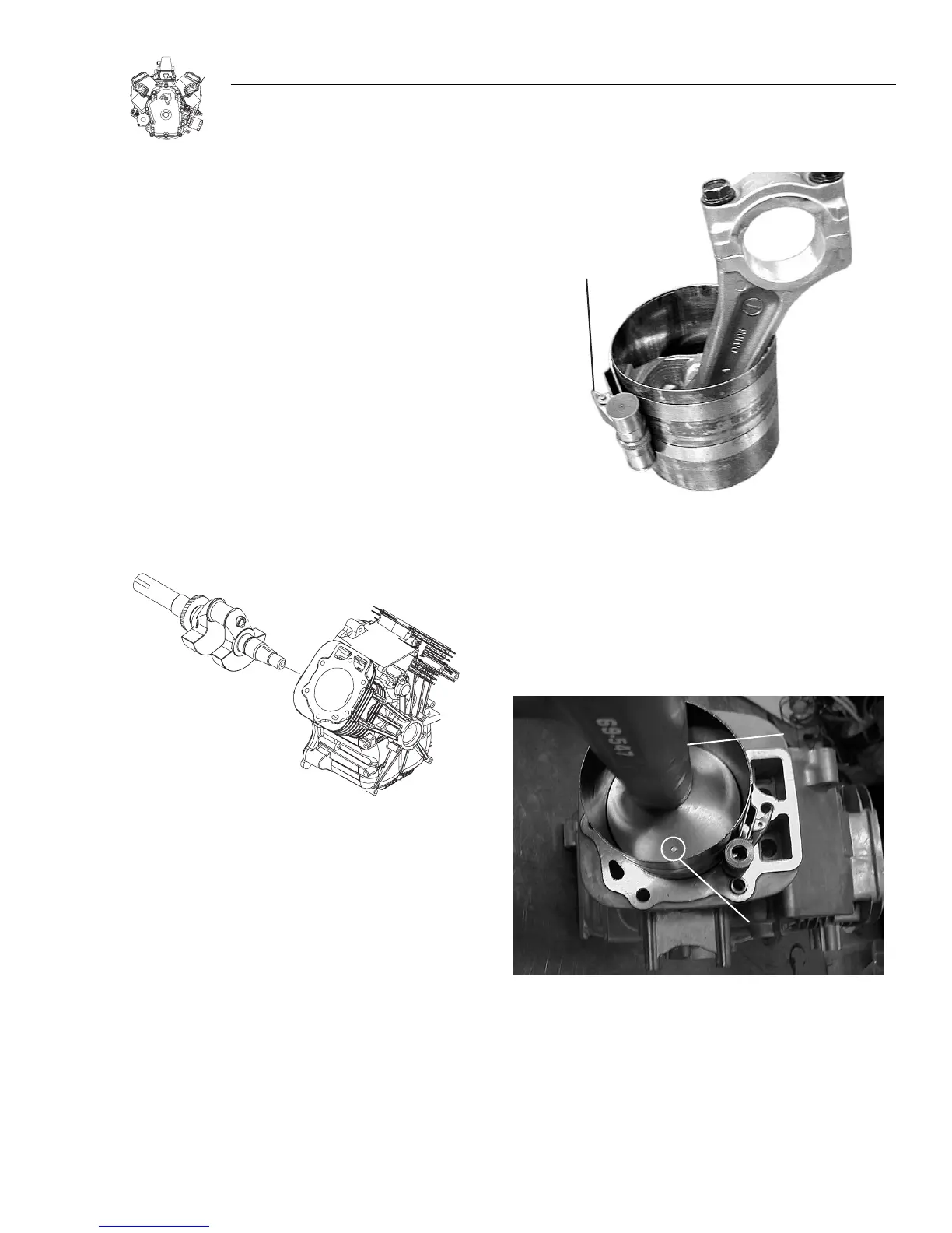
INSTALL PISTON AND CONNECTING ROD
Note: Install #1 piston and connecting rod first.
1. Oil piston rings, piston skirt, and compress rings with Ring
Compressor, Figure 13-2.
a. Rotate the top two compression rings so that the ring end
gaps are on opposite sides of the piston.
b. Place piston and ring compressor upside down on bench
with projections on compressor facing up.
c. Tighten ring compressor evenly until rings are fully com-
pressed.
d. Then loosen ring compressor very slightly so that com-
pressor can be rotated on piston skirt while holding
connecting rod, Figure 13-2.
e. Remove connecting rod cap.
Figure 13-2. Compressing Rings
2. Lubricate cylinder bores and crankpin and rotate crankshaft
until it is at bottom of stroke.
3. Install #1 piston with notch or casting mark towards fly-
wheel side, Figure 13-3.
a. Push piston down by hand until connecting rod is seated
on crankpin.
Figure 13-3. Installing Piston And Connecting Rod
4. Assemble connecting rod cap to rod with match marks
aligned, Figure 13-4.
a. Torque screws to 24.4 Nm (18 ft. Ibs.).

 Loading...