4-1
SECTION 4: GOVERNOR CONTROLS AND GOVERNOR
SECTION CONTENTS
PAGE
MECHANICAL GOVERNOR ........................................... 4-1
GOVERNOR .................................................................. 4-1
GOVERNOR ARM .......................................................... 4-1
STATIC GOVERNOR ADJUSTMENT ................................ 4-2
DYNAMIC GOVERNOR ADJUSTMENT .......................... 4-2
MECHANICAL GOVERNOR
DISASSEMBLE:
1. Drain the oil from the engine.
2. Remove any rust, nicks, or burrs from the crankshaft.
3. Remove the 4 oil cooler screws.
4. Disconnect the wiring from the oil pressure switch.
5. Remove the governor lever from the shaft.
6. Separate the ball joint on the swinging arm.
7. Remove all of the crankcase bolts and slide the crankcase
cover off.
Note: Watch the swinging arm bracket so that it doesn't
hook on the sheet metal.
8. Discard the crankcase gasket & oil passage seal.
GOVERNOR
Both the spool and the flyweights must move freely for the
governor to work properly. Check for wear on the spool and
flyweights. If wear is noticed, change the governor gear
assembly (gear and flyweights), spool, and governor arm.
Lubricate all moving parts when reassembling.
Figure 4-1. Governor Gear Assembly and Spool
1. Force gear assembly and governor spool off of governor
shaft.
2. Remove any remaining plastic from the notch in the gov-
ernor shaft.
3. Check that all the governor bearing parts (top plate, bear-
ing, and bottom plate) are on the shaft, and that it moves
smoothly.
4. Slide the new gear assembly and spool onto the governor
shaft. Slide until the gear hooks into the notch in the gov-
ernor shaft.
GOVERNOR ARM
If the governor arm does not move freely, or if the arm feels
loose in the bushings, it may need replacing. If wear is noticed,
change the governor arm, governor gear assembly (gear and
flyweights), spool, and bushings as needed. Lubricate all
moving parts when reassembling.
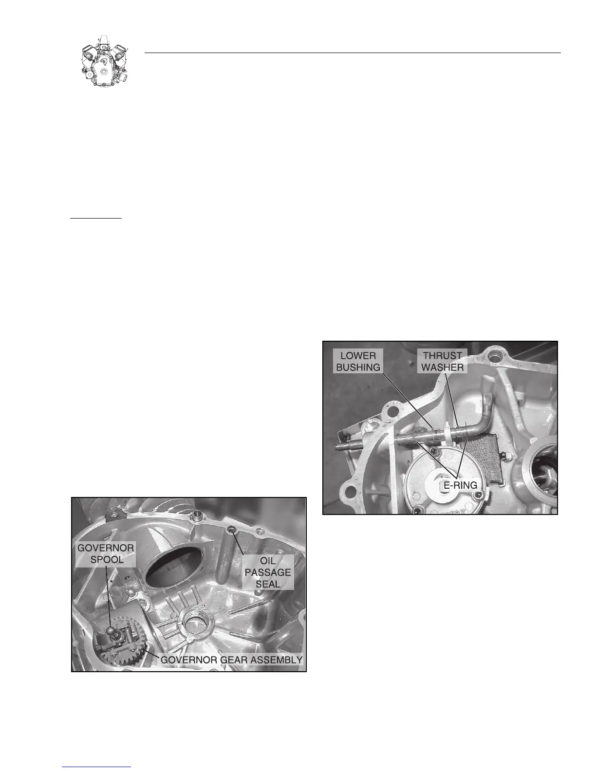
Figure 4-2. Governor Arm Assembly
1. Remove the e-clips.
2. Slide the arm down and out of the bushings.
3. Replace any parts that appear worn.
Note: The lower bushing is a slip fit, and the upper bush-
ing is pressed in.
4. Slide the thrust washer part way onto the new governor
arm.
5. Insert the governor arm in the lower bushing holder, and
slide it part way in.
6. Install lower e-clip on the arm, and slide the thrust washer
down to it.
7. Slip the lower bushing part way on to the arm.

 Loading...