SECTION 5: CYLINDER HEAD AND VALVES
5-6
6. Install rotating screen.
a. Torque screws to 1.9 Nm (17 in. lbs).
7. Install finger guard.
a. If engine is equipped with hex head screws, torque screws
to 4.5 Nm (40 in. lbs).
b. If engine is equipped with finger screws, tighten screws
by hand to approximately 1.3 Nm (12 in. lbs.).
8. Assemble air cleaner.
WARNING: Before starting or running engine, static
adjustment of the governor must be completed!
Failure to make the static adjustments first could
result in engine overspeeding which may result in
engine damage, property damage or personal injury.
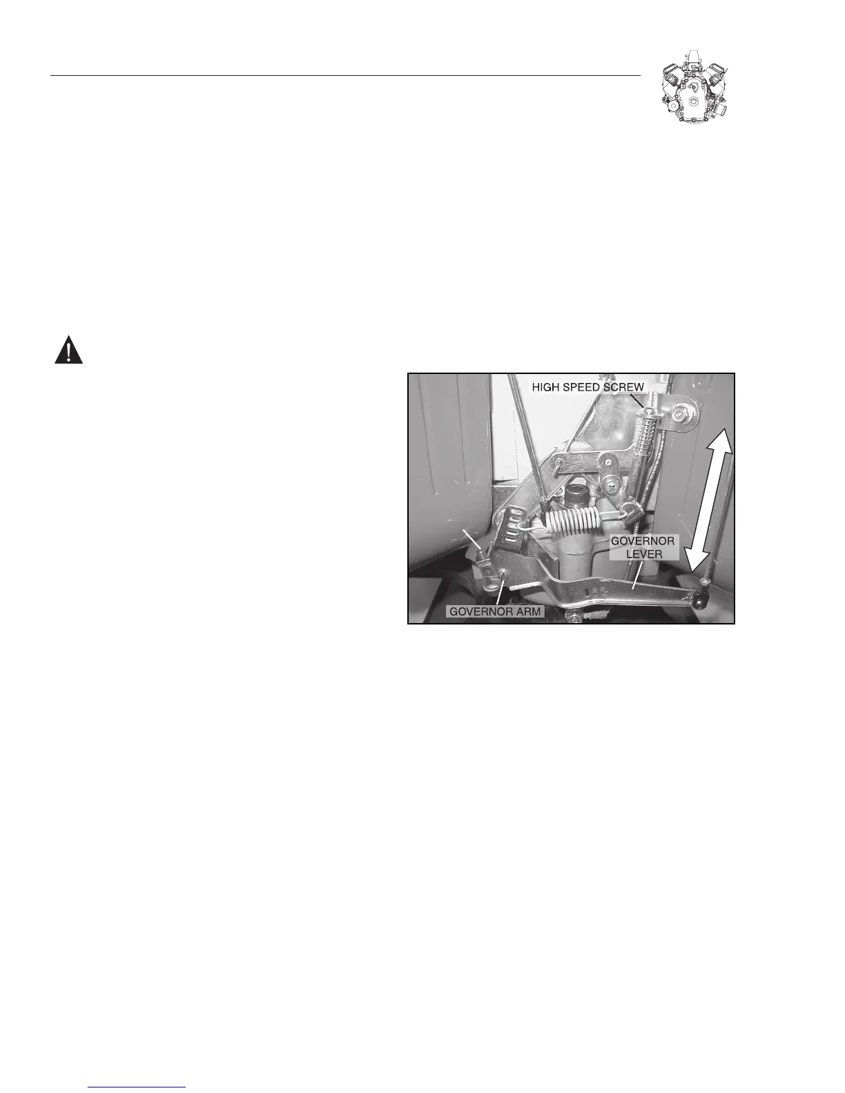
STATIC GOVERNOR ADJUSTMENT
1. With governor lever clinching screw loose, push on gov-
ernor lever until throttle is wide open. Do not bend governor
link or distort governor lever.
2. Rotate governor arm clockwise as far as it will go (Figure
5-20).
a. Torque clinching screw to 11.3 Nm (100 in. lbs).
3. Check to make sure that the throttle travels from WOT to
IDLE. If it doesn’t, the governor will need to be reset again.
4. Install throttle and choke control cables and check for
proper operation.
Figure 5-20. Static Governor Adjustment

 Loading...