1.1 UNPACKING
• Removeall packagingmaterial.
• Removeseparateaccessory box.
• Removecarton off the generator.
1.1.1 ACCESSORYBOX
Checkall contents(Figure1). If any parts aremissing or damaged
locatean authorizeddealerat 1-888-436-3722.
Contentsinclude:
• 2-Axle Pins • OilFilter
• 2- WheelSpacers • Air Filter
• 2- HairPins • SparkPlug
• 2- Wheels • SparkPlugWrench
• 1 - FrameFoot • ShopTowel
• 1 - FrameBolt • 1 Quart SAE30 Oil Bottle
• 1 - FrameFlatWasher • OilFunnel
• 3 - FlangeNuts • 2 - Vibration Mounts
Figure 1 - Accessory Box
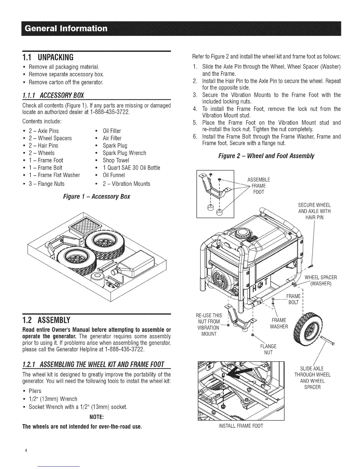
Referto Figure2 andinstallthe wheelkit andframefoot as follows:
1. Slidethe AxlePinthroughtheWheel,WheelSpacer (Washer)
andthe Frame.
2. Installthe HairPinto the AxlePinto securethe wheel. Repeat
for the oppositeside.
3. Secure the Vibration Mounts to the Frame Foot with the
includedlocking nuts.
4. To install the Frame Foot, remove the lock nut from the
VibrationMount stud.
5. Place the Frame Foot on the Vibration Mount stud and
re-installthelock nut.Tightenthe nut completely.
6. Installthe FrameBolt throughthe FrameWasher,Frameand
Framefoot. Securewith a flangenut.
Figure 2 - Wheel and Foot Assembly
ASSEMBLE
FRAME
FOOT
SECUREWHEEL
ANDAXLEWITH
HAIRPIN
t
1.2 ASSEMBLY
ReadentireOwner's Manual beforeattemptingto assemble or
operatethe generator. The generatorrequires some assembly
priorto usingit. If problems arise when assemblingthe generator,
pleasecallthe GeneratorHelplineat 1-888-436-3722.
1.2.1 ASSEMBLINGTHEWHEELKITANBFRAMEFOOT
Thewheel kit is designedto greatly improvethe portability of the
generator.Youwilt needthefollowing tools to installthe wheel kit:
• Pliers
• 1/2" (13mm) Wrench
• SocketWrenchwith a 1/2" (13mm) socket.
NOTE:
The wheelsare notintendedfor over-the-roaduse.
RE-USETHIS
NUTFROM
VIBRATION--_
MOUNT
WHEELSPACER
FRAME
WASHER
FLANGE
NUT
INSTALLFRAMEFOOT
FRAME
BOLT
SLIDEAXLE
THROUGHWHEEL
ANDWHEEL
SPACER
 Loading...


