2.1 KNOWTHEGENERATOR
Read the Owner'sIVlanualand Safety Rules before operating
thisgenerator.
Comparethegeneratorto Figure3 to becomefamiliarizedwith the
locations of various controls and adjustments.Save this manual
for future reference.
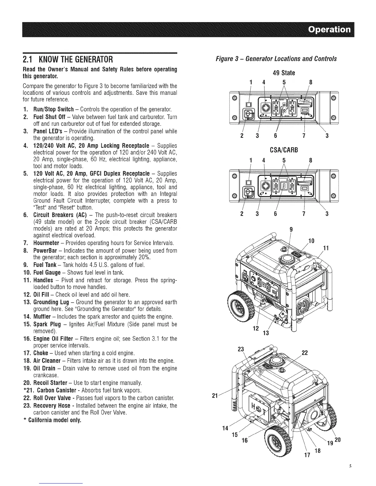
1. Run/StopSwitch - Controlsthe operationof the generator.
2. FuelShut Off - Valvebetweenfueltank and carburetor.Turn
off and run carburetorout of fuel for extendedstorage.
3. Panel LED's- Provideilluminationof the control panelwhile
thegeneratoris operating.
4. 120/240 Volt AC, 20 Amp LockingReceptacle- Supplies
electricalpowerfor the operationof 120 and/or240 Volt AC,
20 Amp, single-phase,60 Hz, electrical lighting, appliance,
tool andmotor loads.
5. 120 Volt AC,20 Amp,GFCiDuplexReceptacle - Supplies
electrical power for the operation of 120 Volt AC, 20 Amp,
single-phase, 60 Hz electrical lighting, appliance, tool and
motor loads. It also provides protection with an Integral
Ground Fault Circuit Interrupter, complete with a press to
"Test"and "Reset"button.
6. CircuitBreakers(AC) - The push-to-reset circuit breakers
(49 state model) or the 2-pole circuit breaker (CSA/CARB
models) are rated at 20 Amps; this protects the generator
againstelectricaloverload.
7. Hourmeter- Providesoperatinghoursfor Service Intervals.
8. PowerBar- Indicatesthe amountof power being usedfrom
thegenerator;each sectionis approximately20%.
g. FuelTank- Tankholds 4.5 U.S.gallonsof fuel.
10. FuelGauge- Showsfuel levelin tank.
11. Handles - Pivot and retract for storage. Press the spring-
loadedbuttonto move handles.
12. Oil Fill- Checkoil level andadd oil here.
13. Grounding Lug- Groundthe generatorto an approvedearth
groundhere.See"GroundingtheGenerator"for details.
14. Muffler - Includesthe sparkarrestor andquietsthe engine.
15. Spark Plug- Ignites Air/Fuel Mixture (Side panel must be
removed).
15. EngineOil Filter- Filtersengineoil; see Section 3.1 for the
properservice intervals.
17. Choke- Usedwhenstarting a cold engine.
18, AirCleaner- Filtersintakeair as it is drawn intothe engine.
19. Oil Drain- Drain valveto remove used oil from the engine
crankcase.
20. RecoilStarter - Useto start enginemanually.
"21. CarbonCanister- Absorbs fuel tank vapors.
22. Roll OverValve - Passesfuel vaporsto the carbon canister.
23. Recovery Hose- Installedbetweenthe engineair intake,the
carboncanisterandthe RollOverValve.
* Californiamodelonly,
Figure 3 - Generator Locations and Controls
49 State
1 4 5 8
@ @
2 3 6 7 3
CSA/CARB
1 4 5 8
2 3 6 7 3
11
12
13
23
22
21
15
16 20
17
18
 Loading...


