Global Power Technologies START-UP AND OPERATION
302842 Rev0 | Sentinel Page 32 of 61
4.4 APPLYING THE CUSTOMER LOAD
Once the Sentinel TEG is operating at the calculated target OCV and all adjustments are completed,
apply the customer load as follows:
1. Connect the customer load to the [ + TEG OUT – ] terminals at the bottom of the main electronics
board.
2. If the low-voltage alarm will be used, connect customer wiring to the [ + LV Alarm – ] terminals.
3. Set the SW200 switch to the “RUN” position.
4. Re-install the electronics enclosure cover plate.
5. Close the instrumentation enclosure door, then secure it by tightening the two door screws.
WARNING!
Make sure that the cover plate for the electronics enclosure is installed and the
instrumentation enclosure door is fastened shut before leaving the site.
4.5 RECORD KEEPING
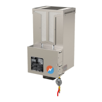
Your Sentinel TEG is now operating successfully, providing continuous electrical power to the
customer load. For ease of maintenance and service, keep a record of the unit’s performance using
the MAINTENANCE AND PERFORMANCE LOG provided at the end of this manual. Record all
parameters each time adjustments are made and when maintenance or service is performed on the
unit.
4.6 SHUTDOWN
The Sentinel Thermoelectric Generator is intended for continuous operation where reliable power is
required without interruption. If the TEG must be shut down temporarily for servicing or an
emergency, close the TEG manual shut-off valve. To ensure there is no voltage present at the screw
terminals on the board, turn SW200 to OCV (refer to Figure 3) and disconnect battery connector from
battery PCB (refer to Figure 11).
 Loading...